Building a DB BR140
140.425 is on a passenger service to Nürnberg at Bamberg on 22nd July 1971.
For my next scratch building project I've decided to attempt a model of one of the standard Deutsche Bundesbahn Bo-Bo electric locomotives. Visually, the express class BR110s and the freight/ mixed traffic BR140s were almost identical apart from the paint colour: BR110s in dark blue and black and BR140s in green and black. I've decided to build the BR140 as I remember them from my visits to Germany in the early 1970s with the rain strip running around the roof. Later these were removed and altered the locomotives' appearance somewhat.
The model will be built entirely from plans and without any help from the pdf kits I've used before for diesel and electric locomotives. The major difficulty I foresee is making the cab fronts, with their subtle curves, in cardboard.
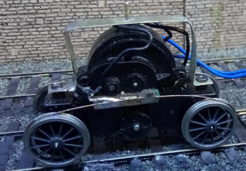
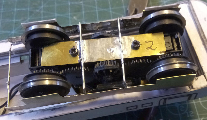
Construction starts in a similar manner to my BR144 using Airfix/ Hornby tender drive units from a Fowler 4F 0-6-0. The plastic wheels with their integral gears are removed from their axles and S Scale axles substituted. Some Alan Gibson S Scale 4'3" tender wheels are the mounted on the ends of the axles.
A bracket from a length of brass strip is bent into an inverted U shape and then each leg is bent outwards to form an L shape. Holes are drilled in the strip to allow the brass to be secured to the tender drive unit using the self tapping screws that secured the weight. A brass bolt is passed through a hole at the top of the bracket to act as a pivot.
The original gears are therefore used although I have cut away most of the plastic from the centre wheels to improve the appearance of the bogies when complete.
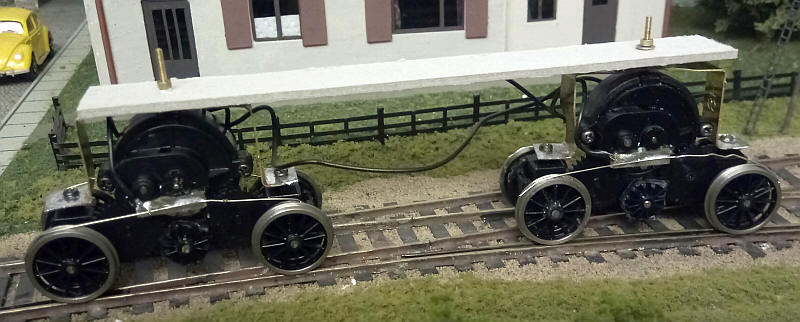
In the photo above the bogies have been secured to a temporary strip of card for testing purposes.
As the BR140 had disc wheels, unlike the BR144, I'll add discs of card to the face of the wheels before building the bogie side frames.
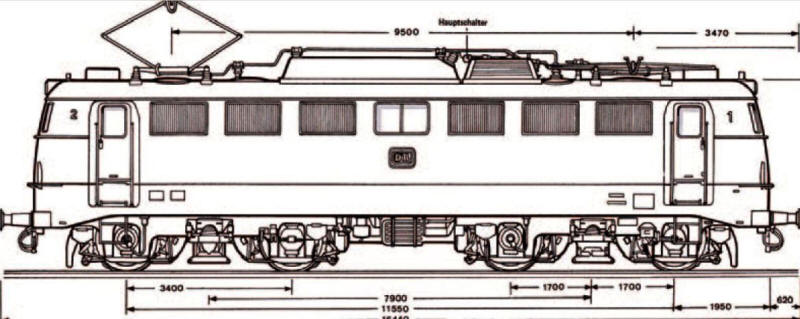
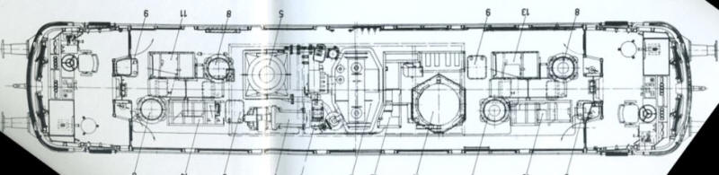
Diagrams for the BR140 were found on the Internet and resized to S Scale.

These were printed out on good quality card and the lower part of the body - the main frame was cut out.
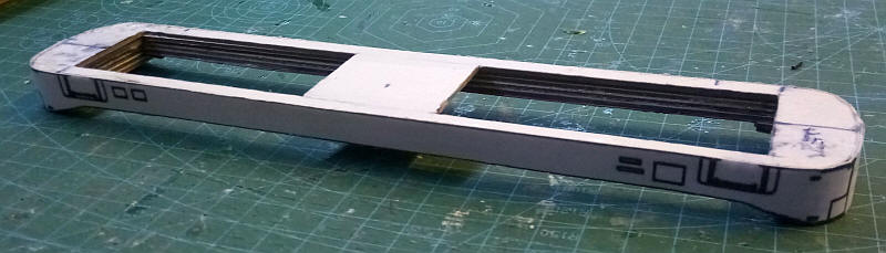
I've now completed the frame. The flat top was cut from a piece of thick mounting card. I cut this slightly narrower than the width of the loco to allow for the multiple layers of the frame sides. Holes were cut in the top to accommodate the motor bogies.
The ends of the frame sides were wrapped around the ends and numerous strip of mounting board were glued inside the frames to ensure that everything was at right angles or curved in the correct way. Before continuing the whole framework was given several coatings of wood hardener.
To mount the motor bogies I've built a cuboid box out of thick mounting card. The bottom of the box has been left open whilst there are two holes in the top of the box to accept the pivot bolts. The box was then glued to the locos frame. Careful measurement using a simple card jig ensures that the top of the frame is the correct height above the rail head. To strengthen the pivot holes small piece of brass with a hole drilled through will be glued to both sides of the top of the box.
The spoked wheels have been covered with small discs of card glued to the face of the wheel and painted black.
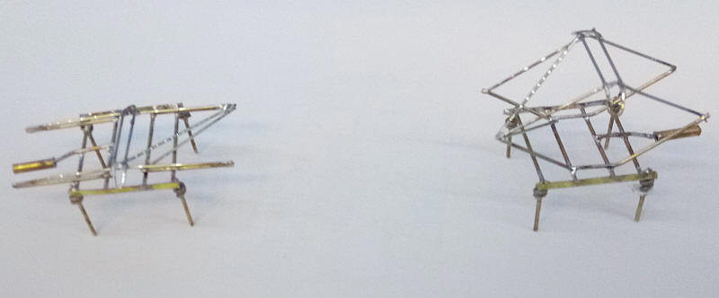
Before starting work on the body I decided that I needed to find a way to attach the bogie side frames. A piece of sheet brass was secured to the underside of the motor bogies using the screws that hold the bogie keeper plate. Sheets of brass were cut roughly to the outline of the bogie sides and soldered the brass sheet with lengths of nickel silver wire as can be seen in the photos. The brass sides were also strengthened and joined together at one end using a length of wire bent into a |_| shape. The end of the bogie closest to the ends of the loco can't have cross wires because of tight clearances.
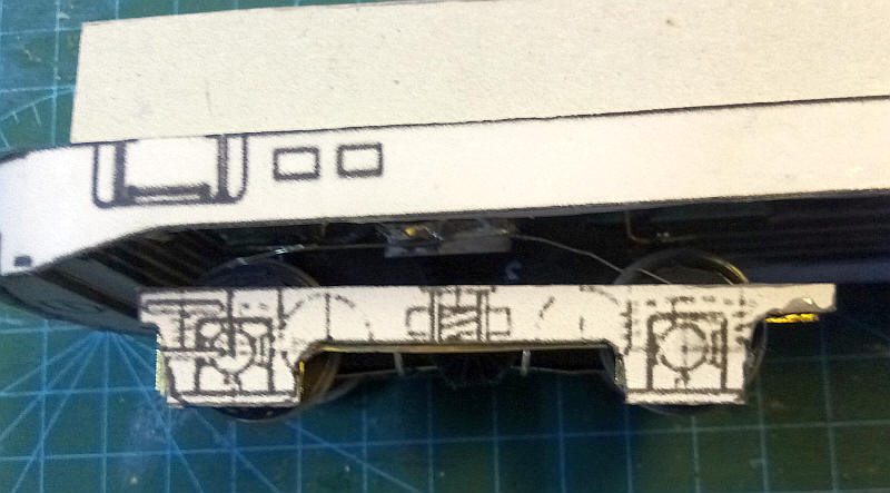
The card print out of the bogie sides was glued to the brass sides of the bogie. This will later have all the necessary details added to it.
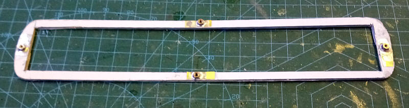
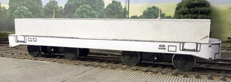
The loco's body will be a separate and removeable part. In the photo the baseplate for this had been cut out from a sheet of mounting board at the same time as I prepared the loco frame so it is identical. The body will drop over the "box" that hides the motor bogies and will be held to the frames with nuts and bolts. Holes were drilled through the ends and at the mid point of the sides to allow bolts to be passed through the frames. At this stage the body base is very flimsy but it will soon be strengthened
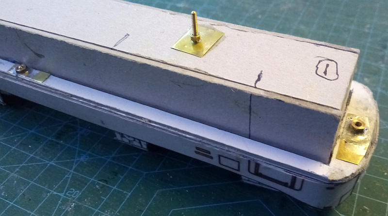
The baseplate of the body is now in place showing how its is a fairly tight fit around the "box". The securing nuts are soldered to small pieces of brass which are superglued to the base of the body
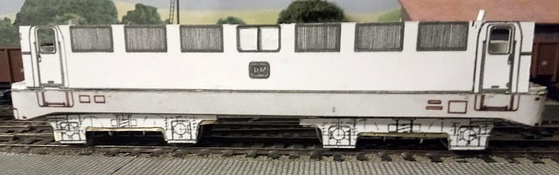
The first body side has been added to the baseplate. The doors on the real loco are slightly recessed so This has been replicated by adding layers behind the main central section of the body side. The side was then reinforced with several layers of mounting card.
Both sides of the body have now been added. Reinforcement strips of mounting card have been added on the insides and inverted U shaped strengthening pieces have been added to the ends of the main body section to ensure that the sides are vertical.
A piece of mounting board has been cut to fit snuggly inside the sides. Note the ends have had a section of the card removed as the ends above the cab will have a piece of brass cut to match the tops of the windows. The brass will be secured to the card.
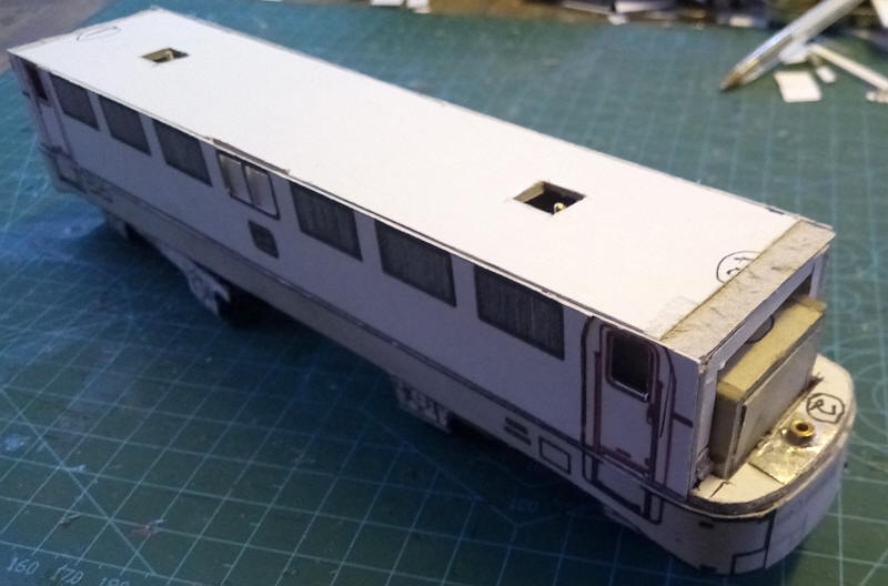
The brass sheet which will form the strengthening piece above the cab windows has been cut the correct shape and secured to the top of the body.
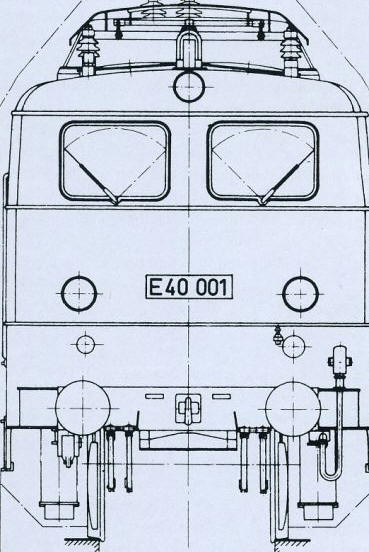
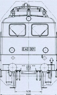
The drawing of the front of the loco was printed out several times of thin card ready for assembly.
I've now added the lower half of the cab fronts. It's not obvious from the photo but the card slopes correctly inwards at the top very slightly.
I've decided that the cab windows will not have glazing in the normal way but will have a card backing onto which I will add "glue and glaze" to give the impression of windows. The reason for this is that the box hiding the power bogies comes too far forward in the body and in any case the windows are very close to the edges of the card and will lack strength.
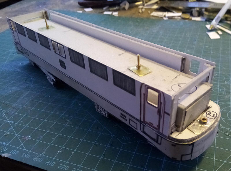
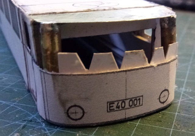
To make the top half of the cab stronger I've added two short lengths of brass tube at each corner to give some support for the card which will have the windows in. The zigzag flaps will support the card at the joint between the top and lower halves of the cab front. A similar flap was also added to the underside of the brass roof extension.
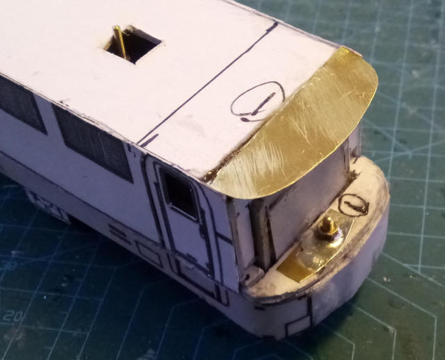
The next stage was to add a strip of thin card wrapped around the upper part of the cab front.
The outer layer was then added with the windows cut out very carefully. I used super glue as an adhesive as it leaves no trace when applied carefully and also strengthens the card itself.
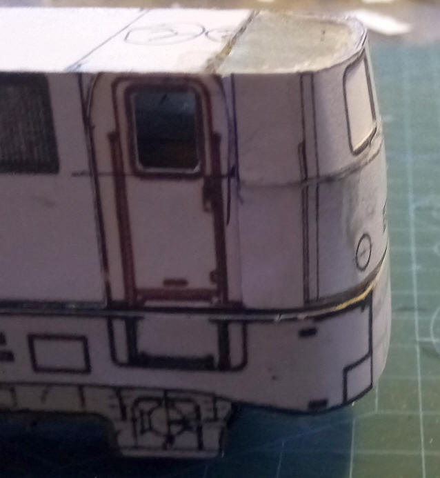
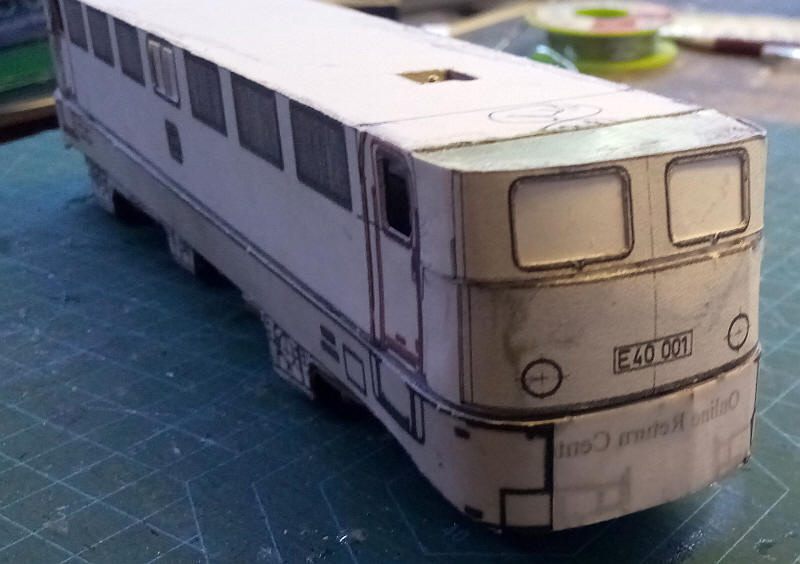
As can be seen the card is bent around the ends and also angles backwards to give a reasonably good impression of the actual cab. I used a template cut from the diagram to check this. Note that there are several printed lines in unusual places at the ends - this is a result of using the original diagram printouts.
I've built the roof using my usual method of layers of mounting card of reducing width covered with two layers of photocopying paper (see the BR V160 and BR E44 for more details) . The dome ends are built similarly but the card is then covered with filer shaped and filed to the correct profile. The upper headlight is a length of brass tubed inserted in a hole drilled in the front of the roof.
The buffer beams are from two layers of card slightly recessed into the front of the main frame. The ends of the buffer beams are folded and glued the curved ends of the frame. The resulting triangular shaped gap has been filled with two part epoxy.
A thin strip of microstrip plasticard has been used to form the rain strip around the joint between the roof and body sides.
Another strip of microstrip plastic has been added around the lower part of the body. Once the body is painted the plastic will be scraped to give the white line that ends all around the loco.
Buffers are cast metal BR heavy duty ones which be given larger heads made from sheet metal.
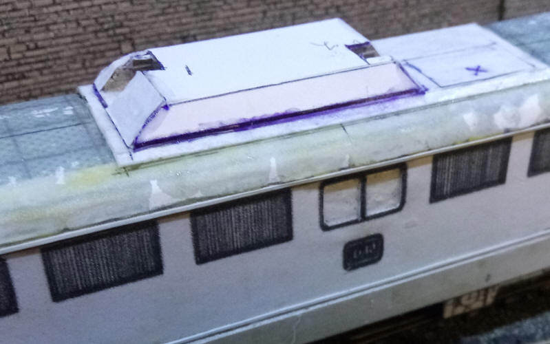
I've now added the unusually shaped raised area on the roof. The sides and ends slope at various angles and there are cut outs at both ends. The outer layout is supported with multiple layers of card to give a solid structure on which various pieces of electrical gear will be mounted.
I haven't been happy about not having the front windows not glazed properly so I've now carefully cut out the layers of card.
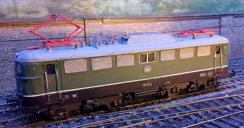
The two pantographs have been built so that one is raised and the other lowered. Modern DB electrics almost always ran with only one pantograph raised (but non functioning).
The pantographs were built in a simple jig with four holes drilled through a piece of chipboard. Lengths of 1mm brass wire were placed in the holes and joined together at the top with strips of thin brass. Four cross pieces of 1mm wire were soldered between the strips as temporary spacers and the rods at the bottom of the pantograph arms that are used to raise or lower them. Once in place on the roof the two outer crosswires were removed as they were only intended to help maintain rigidity during construction
The lower legs of the pantograph were bent to shape from 0,9mm nickel silver wire whilst the upper legs and cross bracing were from 0.7mm wire. The contact strips were bent from 0.7mm nickel silver to give the distinctive open shape with curved ends that drop down at the ends. A piece of wire was soldered to a length of brass tube to represent the pantograph raising mechanism. Coils of solder were used to represent the insulators under the frame.
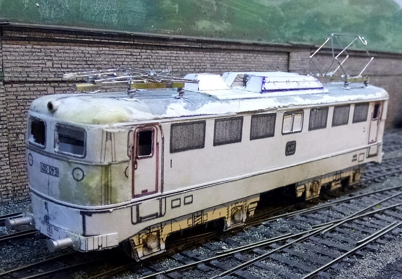
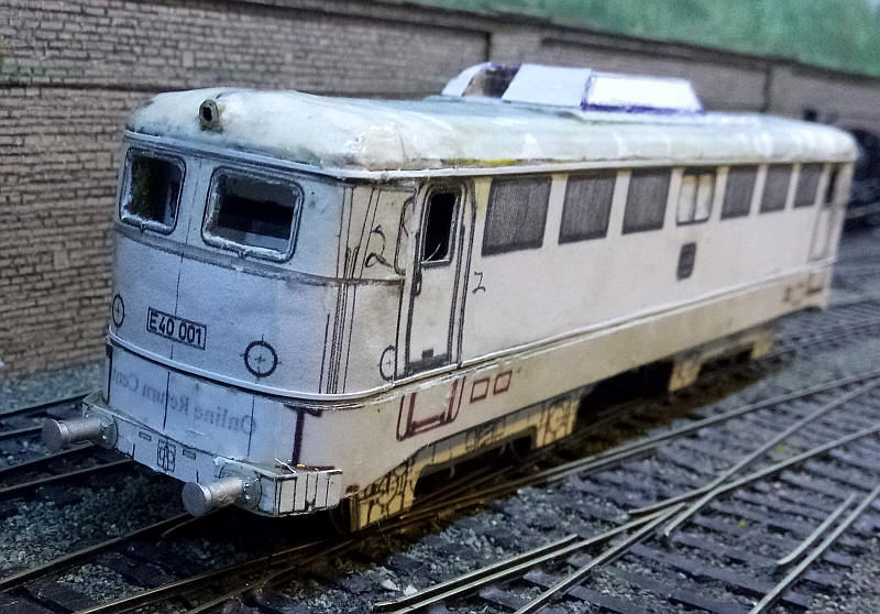
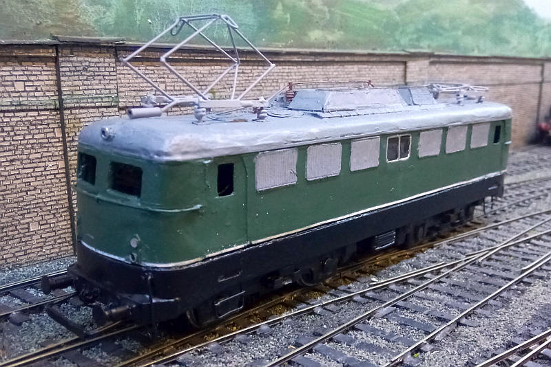
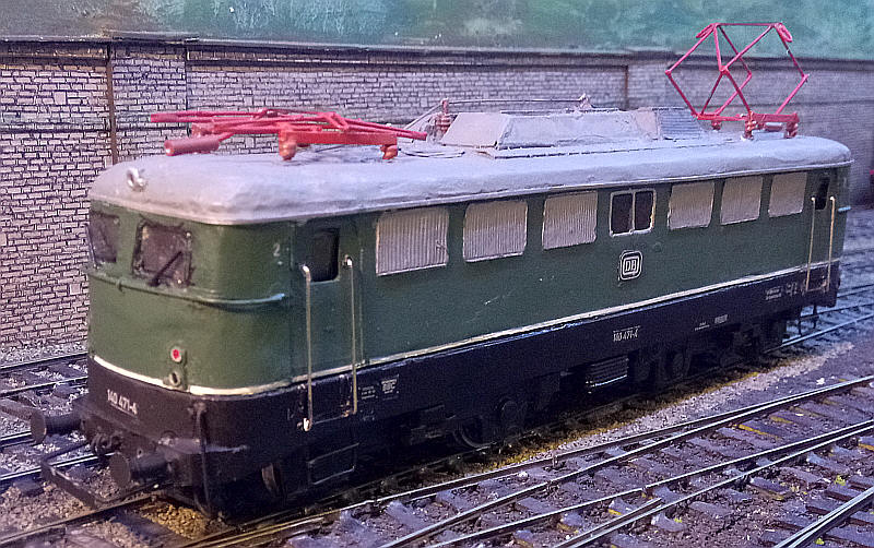
The views above show the pantographs temporarily installed. The frame "legs" slot into holes drilled in the roof. I've also added the smaller raised area on the roof as well as some details on the bogie frames.
In this photo and the one below a lot of detailing work has been added out of card, plastic strip and nickel silver and brass wire.
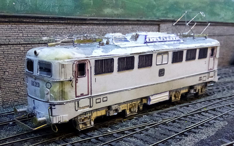
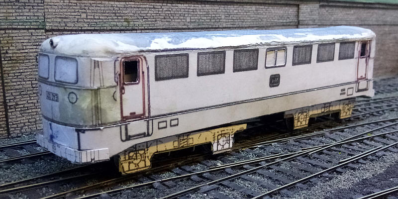
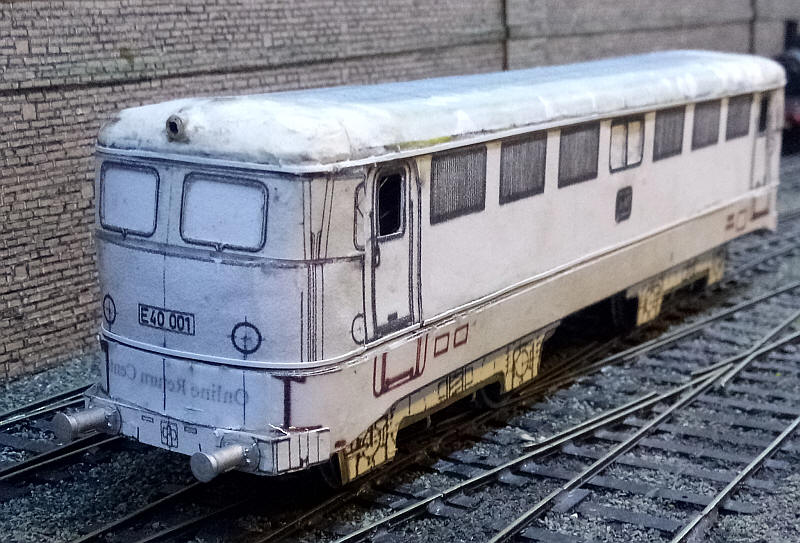
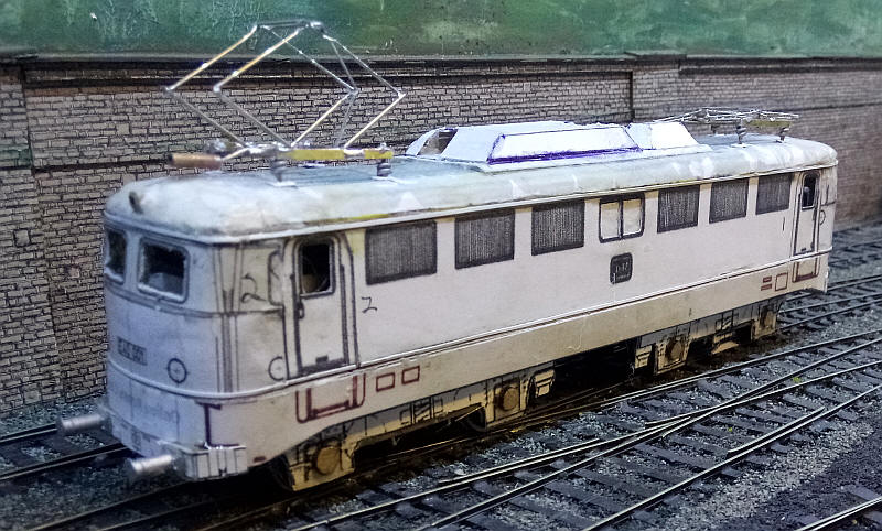
The body and undeframe of the model have been painted and the paint over the plastic strip along the bottom of the body has been scraped away to reveal a well defined band.
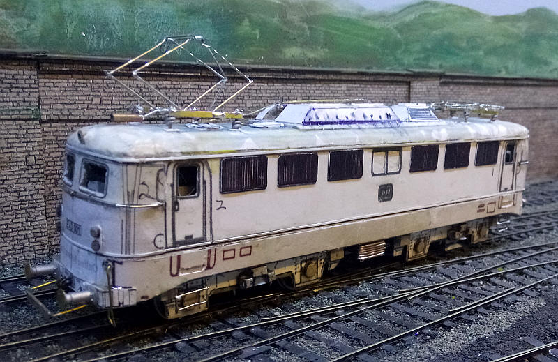
The completed model with transfers from Modellbahn Decals. There are numerous faults - cardboard modelling is both easy and difficult to use as a material! As usual photographs reveal problems not immediately obvious.
The cab windows were made from clear plastic held in place with 'glue and glaze'. This doesn't dry completely clear so tends to leave a slight smearing on the glazing. The cab handrails have to bridge the gap between the body and underframe. The nickel silver wires are secured at the top to the body and at the bottom they simply pop into holes drilled in the frame sides.