Building a DB BR V90 (BR 290)
Having already built a pair of DB's V100 Bo-Bos it seems logical to construct a model of the larger V90 locomotives using similar constructional techniques.
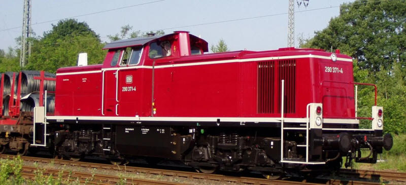
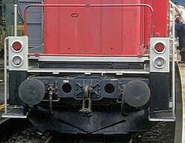
The V90 (later BR 290s) were intended for freight operations both in marshalling yards and as power for freight trains on the main line, especially "trip" workings between industrial premises and marshalling yards.
The photo above is reproduced under the Creative Commons License and is from this webpage:
https://commons.wikimedia.org/wiki/File:Museumslokomotive_290_371.JPG
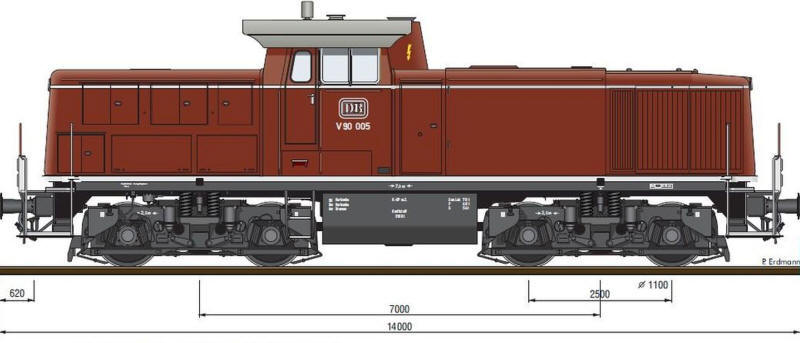
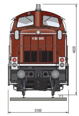
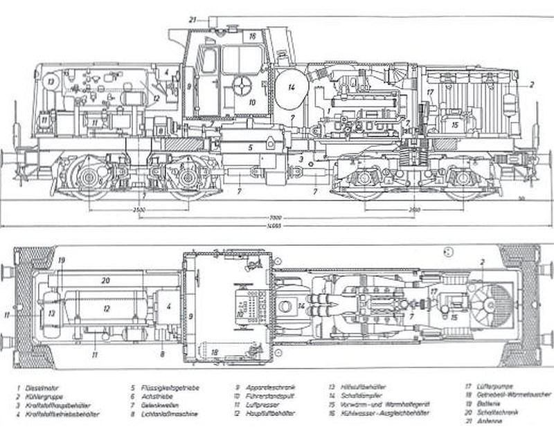
Models obviously need scale drawings and these shown above are taken from a long out of print book about the class published by Eisenbahn Journal.
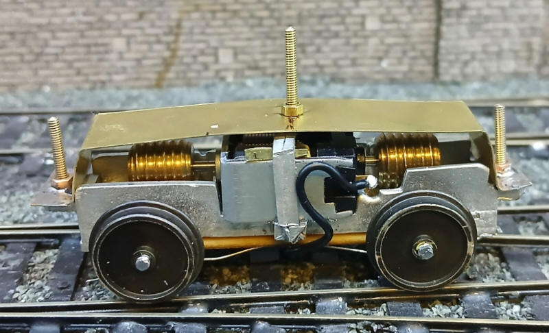
Construction starts with adapting the former BEC tramcar bogies as power bogies (now sold by KW Trams - http://www.kwtrams.co.uk). In S Scale the V90s should have a wheelbase of 39mm so I choose to use the 40mm tramcar bogies.
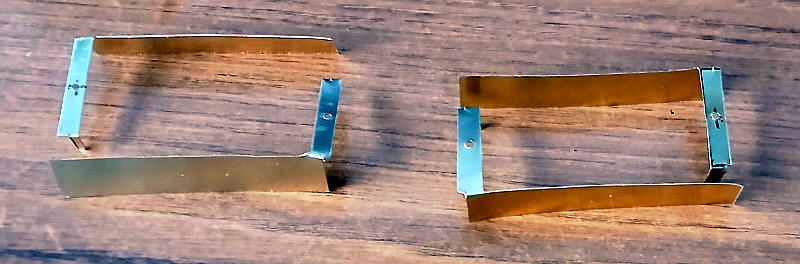
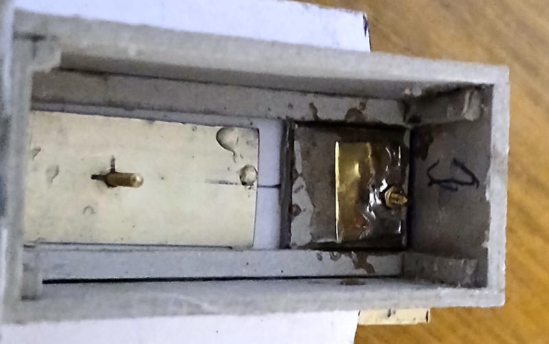
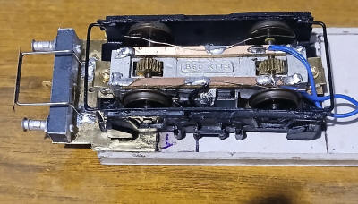
The photo above shows the simple bracket that I cut and folded from a strip of brass. The bracket is held in place with bolts passed through the securing lugs at each end of the white metal frames whilst the pivot point is another bolt located above the motor securing bracket.
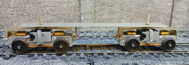
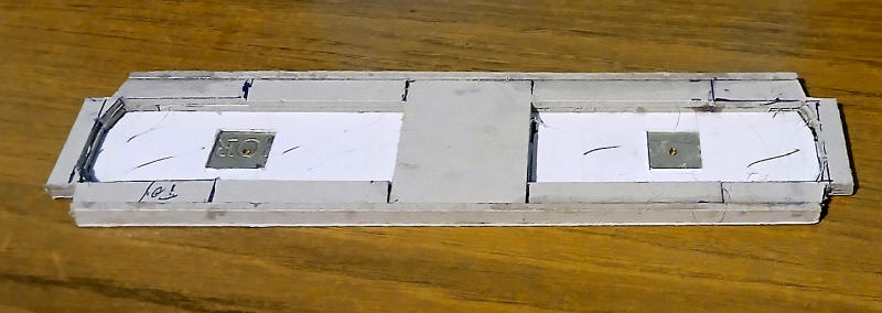
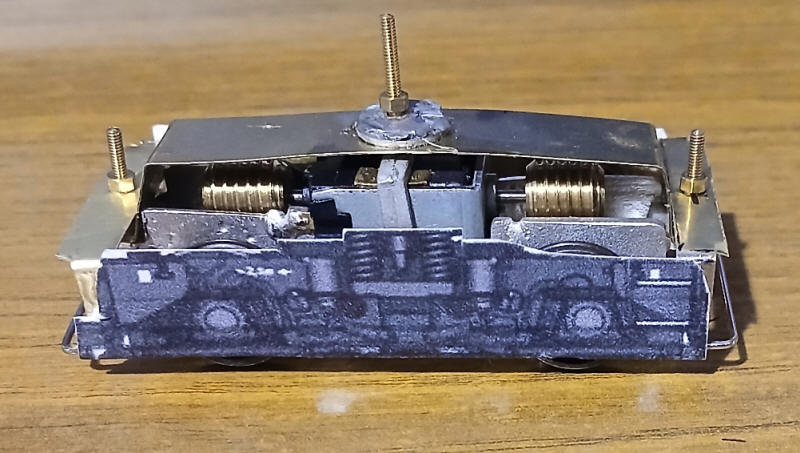
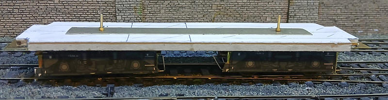
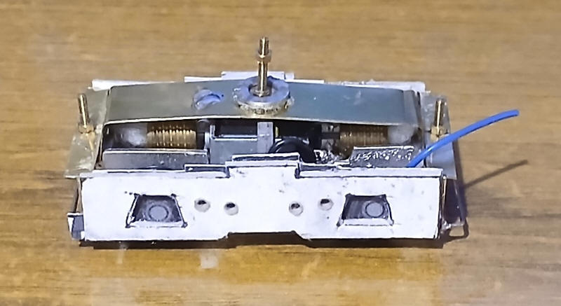
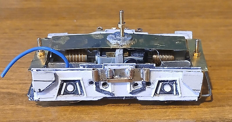
The two motor bogies have now been connected to form a working chassis. A length of nickel silver strip about 15mm has had holes drilled for the pivot points for the bogies. Two large washers were placed between the motor brackets and the nickel silver strip. This should give additional stability to the loco body and prevent it wobbling when the loco moves.
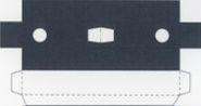
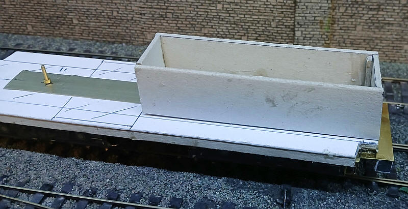
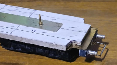
Using the re-scaled diagram shown above a piece of thick card was cut out to form the top of the footplate that runs around the top of the loco's frame. The shaded areas were removed as they are the cut outs for the shunter's steps. The centre line and position of the bogie pivot bolts were marked and then......
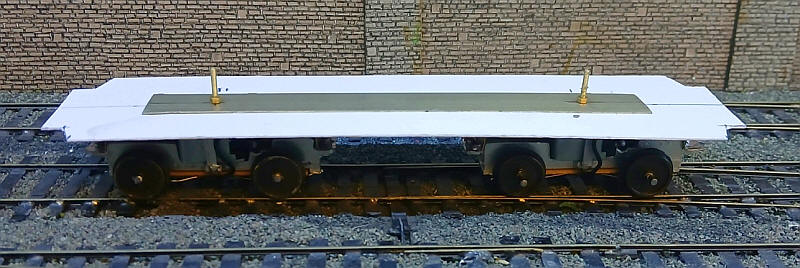
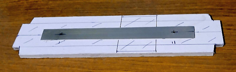
....the card was glued underneath the nickel silver strip. By chance this gives exactly the correct height (25mm) above the rail head.
The footplate frame has now had its sides added - 5mm strips of greyboard added along each long side. This has then been strengthened with further strips of greyboard behind the outer piece.
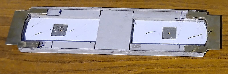
The ends with the extension where the bonnets finish and the recesses for the shunters' steps have quite a complex shape to allow for the swing of the bogies.
All these strips have overlapping joints to make the frame as strong and rigid as possible.
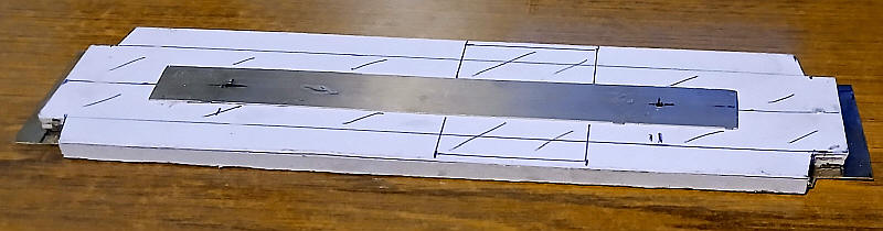
This view is the footplate frame from above/ I've marked in the position of the two bonnets and the cab as an aid to the construction of the body.
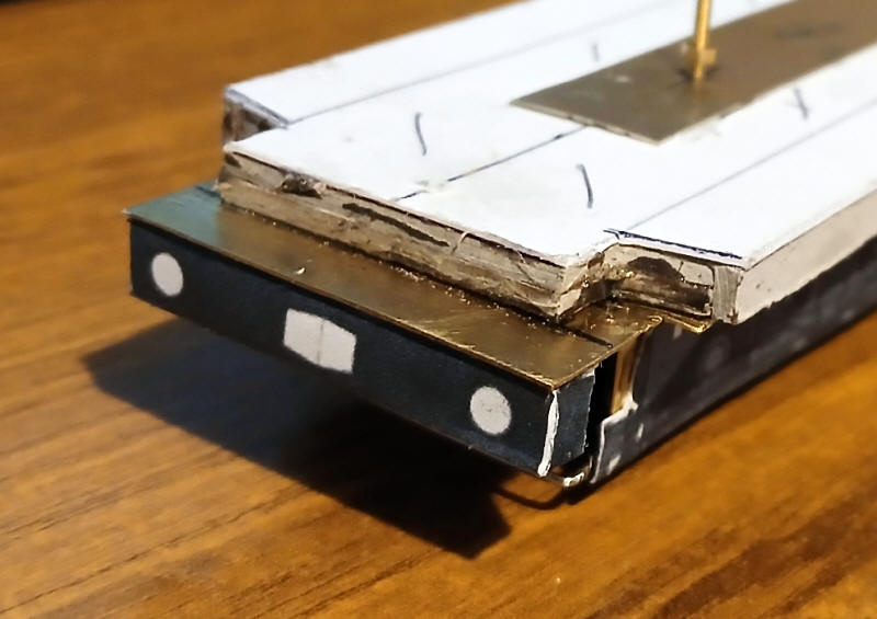
In order to make the shunters' platforms at the end of the locos strong enough I decided to make these out of brass sheet. These have quite a complex shape as they also form the upper step at the ends of the loco but also have to have a sufficient area to attach the brass to the footplate card frame. They also need to be strong enough to attach the buffer beams and the loco's couplings.
A further factor is the need to have a hole drilled through the brass and the footplate to allow the bonnets at the ends of the loco's body to be secured in place.
The shunters' platforms viewed from above.
I've now turned my attention to the bogies. For the bogie sides I am using brass sheet cut and soldered to form an inner frame on which the detail parts will be added from card, plastic and wire.
The first stage is to cut an "L" shaped piece of thin brass and fold it as shown in the photo above. The frame will be held in place by the bolts already in place on the bogie.
 |
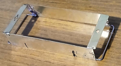 |
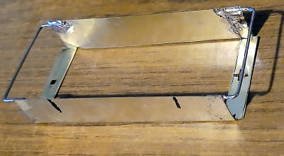
The two photos above show the assembled inner frames (left photo shows looking from the bottom whilst the one on the right is from the top) . Nickel silver wires has been soldered across the ends at the bottom of the frame in order to give some rigidity.
Having printed out the bogie side frames from the diagram at the top of this page they have been glued to the brass inner frames with epoxy. The height is easily adjusted by adding an extra nut as a spacer to the bolts before tightening the fixing nut in place.
The running chassis has had its first and satisfactory run.
The buffer beams on the V90 are similar to those on the V100 so I have used the parts from the pdf kit from that model. The net shown above is cut out and folded with strips of greyboard slotted inside the buffer beam to give it rigidity.
The buffer beam is then glued to the underside of the brass shunters' platform.
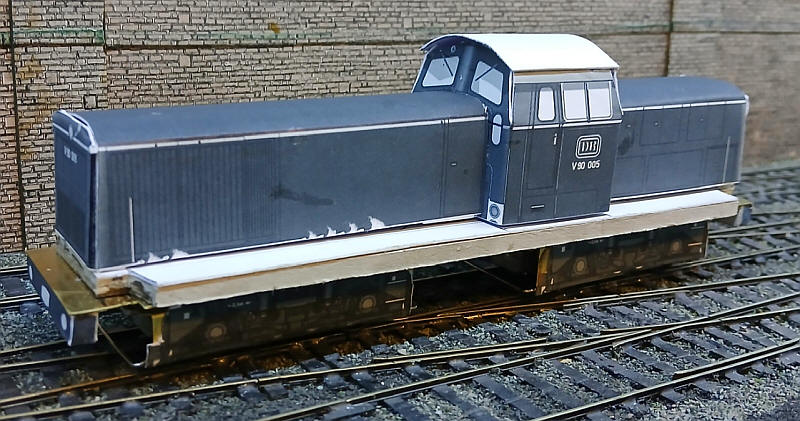
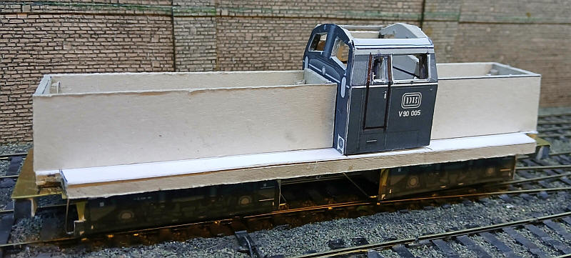
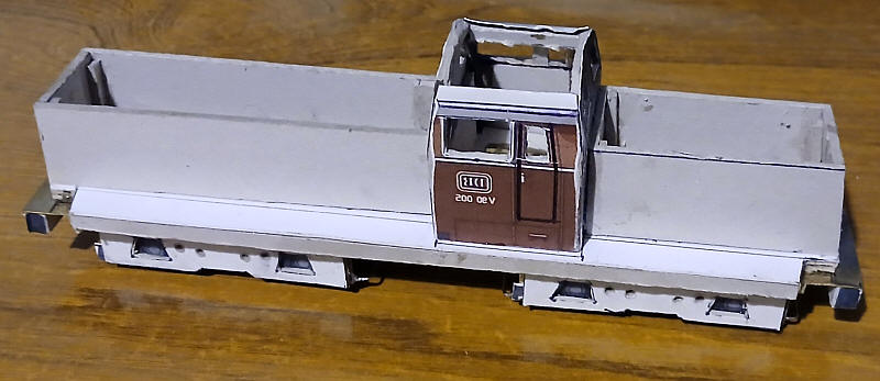
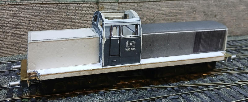
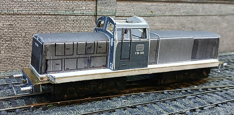
Before taking construction any further I thought it best to make up a mockup of the body to see if everything would fit and that the overall impression of a V90 would be captured.
Using the coloured diagrams from the book about the V90s I cropped sections of the diagram and combined them to make a series of nets which I printed out on paper and then stuck to thin card. These were then folded into shape and the two bonnets and cab glued together to male the mock up body.
 |
 |
 |
|
The substructure for the long bonnet has been made up out of greyboard.
The cab has now been assembled. The sides and ends were printed onto thin card and the window openings cut out, leaving the window frames in place to allow fixing of the glazing at a later stage. The thin card was then glued to 2mm grey board and the window openings cut out again. For the cab front and rear pieces the backing card was cut 2mm narrower on both edges so that the thin card will overlap the ends of the cab sides and give a neat finish. Small strengthening strips were glued inside the cab in the corners and above the windows.
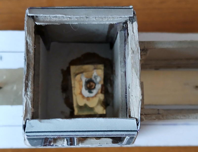
To secure the cab to the chassis I've used a different technique. A hole was drilled through the nickel silver strip on the top of the chassis and also through the card of the cab floor. A 10BA nut was soldered to a sheet of thin brass which had a hole drilled through it. This was then glued to the cab floor with epoxy and a 10BA bolt passed through the hole in the chassis.
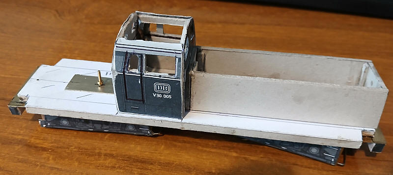
The corners on the cab have been rounded slightly by filing. The long bonnet and cab have been glued permanently together.
The short bonnet substructure has no been glued permanently in place.
To secure the bonnets to the chassis I've used the same method as in the cab. A piece of brass has been glued to the base of the bonnet and a nut for the securing bolt has been soldered in place. The bolt has been passed through a hole drilled through the main frame just behind the buffer beam.
It will be possible therefore to separate the body from the main frame by unscrewing the three bolts.
The basic heavy metal frame is represented by pieces of 2mm thick card cut to the basic shape of the bogie side onto which other pieces will be added.
Openings have been cut where the axle boxes will be whilst 4 holes have also been drilled through the card.
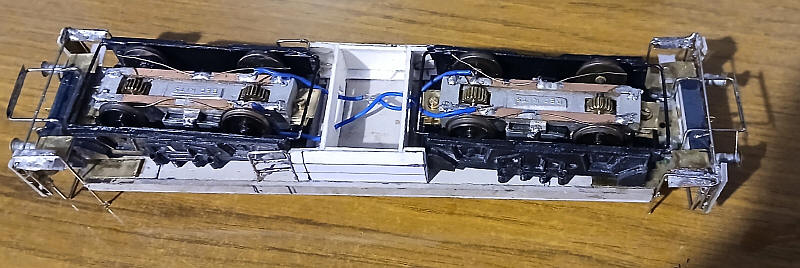
The bogies have now been given some detail parts. The various parts have been added from a mixture of card, plastic strip, brass sheet, tube and shortened bolts. In total there are 29 parts needed for each bogie side.
The bogies have now been sprayed and remounted onto the frame. I've also linked the two bogies together electrically so the model picks up current off all wheels.

For comparison this is an O Scale model.
 |
 |
For the V90 the distance between the front of the bogie and the buffer heads is too great for the method I used for fixing the couplings on the V100s to work. So instead of using a tension lock coupling from Bachmann or Hornby I'm using a simple wire coupling bar. This is bent up from 0.9mm nickel silver wire and is soldered to the brass sheet under the buffer beams. Its quite a complex folding job with six bends needed. I've also soldered a 3mm wide strip of nickel silver to the wire which will act as a buffing pad when propelling vehicles fitted with the standard couplings. The buffers are white metal castings of BR heavy duty freight wagon buffers.
This photo shows the next two stages of construction of the loco body. On the left (the short bonnet) I've now added a few extra strengthening pieces of grey board inside the bonnet sides and then added another piece inside the top.
I had already made the bonnet wrappers when I made the body mock up so I printed them out again on thin card and using a biro point I scored then vertical lines for the large ventilation louvres that are to be found on the long bonnet.
The long bonnet also had another layer of greyboard cut to the exact size of the bonnet top. I cut the edges at about 45 degrees to give the rounded effect of the edges and corners and then glued it in place. The external card wrapper was then folded and glued in place and, to my surprise, fitted perfectly.
The process was repeated with the short bonnet. The door openings on this part of the model were again scored heavily with a black biro tip. The depression for the door handles were also impressed into the card in the same way.
The next step was to fit the bonnet ends. They are slightly different at both ends. This is the short bonnet end with 4 doors and 4 ventilation louvres. The long bonnet has just three doors.
The next two photos show the next stages.
The bonnet ends have been fitted with the card wrapped around the curved corners of the bonnets. The ends have had a coating of superglue applied to corners to harden the card in this area. The curved tops of the front of the bonnets will be filled with filler. On the long hood an additional wrapper has been glued over the bonnet. I believe this was a removable section.
Building the shunters' platform and steps is one of the parts of construction that I hadn't been looking forward to.
The first step is to make the foundations for the distinctive light brackets on either side of the buffer beam.
These were cut from brass sheet (about 20mm by 5mm) with a small tab on one side. The tab was bent at right angles and then glued to the end of the card bufferbeams.
Obviously this was not a strong joint so I joined the lower edges of the light brackets along the bottom edges with a length of nickel silver wire soldered to the rear of the brass. This is unprotoypical but necessary for strength. I then added another length of nickel silver wire a couple of millimetres above the bufferbeam - this is present on the real locomotive. A U shaped length of wire, which forms the safety rail for the shunters was also soldered on to the rear of the light brackets. And yes I realise that the brass sheet on the right is not straight of the same as the one one the left. The cosmetic lamp bracket will hide this when I add it.
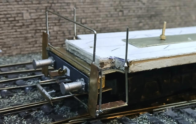
The vertical handrail was passed through a small split pin which is secured in a hole drilled in the card footplate. The bottom of the wire was also bent to form the support for the lower footstep which is simply a strip of brass sheet. Soldering all the joints together results in a secure structure. At this stage it all looks rather crude but once the cosmetic light brackets is added and the whole lot painted black things will look much better.
Now I just have to repeat the process at the other end of the locomotive.....
The fuel tank and cab steps have been added.
The fuel tank is made up of card bent to the correct profile and two cross pieces to hold the sides in place.
Slots have been cut in the cross pieces to allow the wires to be feed through. There is also space here for some weight if I find that is needed.
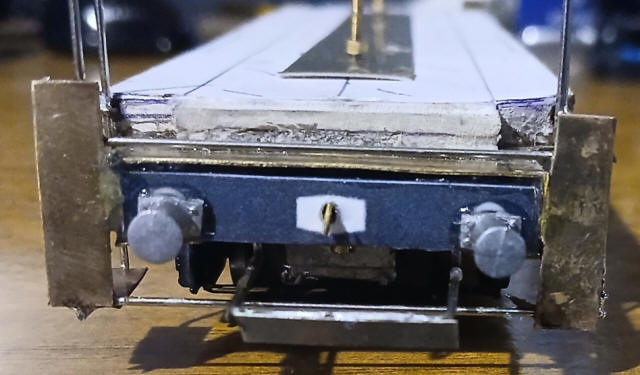
At the ends of the locomotive large buffer heads cut from thin brass sheet with a hole punch have been added to the rather puny cast metal buffers.
Finally the light consoles have been made from thick card glued to the brass foundations. Small plasticard discs have been added to represent the headlights.
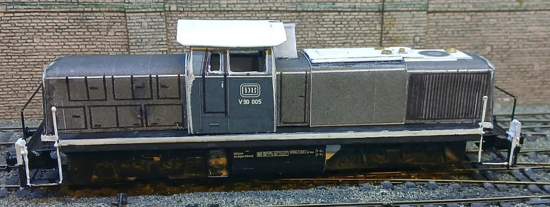
I've now completed most aspects of the chassis. A strip of plasticard has been solvented on to the card running plate and the chassis sprayed matt black. The handrails and light console assemblies painted white. The transfers found on the side of the fuel tank have been applied.
On the long bonnet the various detail parts have been added from card, plastic strip and brass bearings and washers.
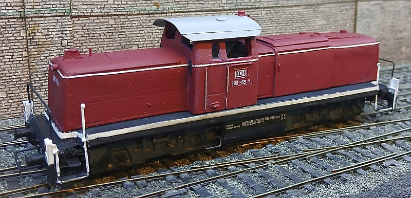
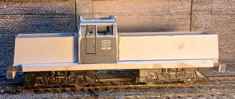
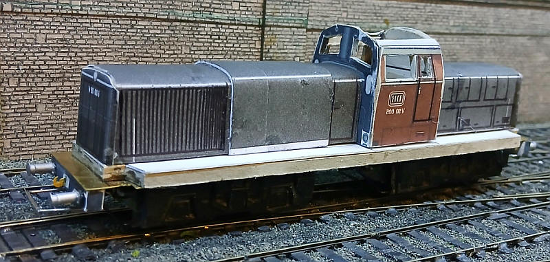
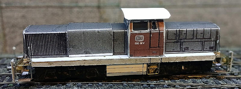
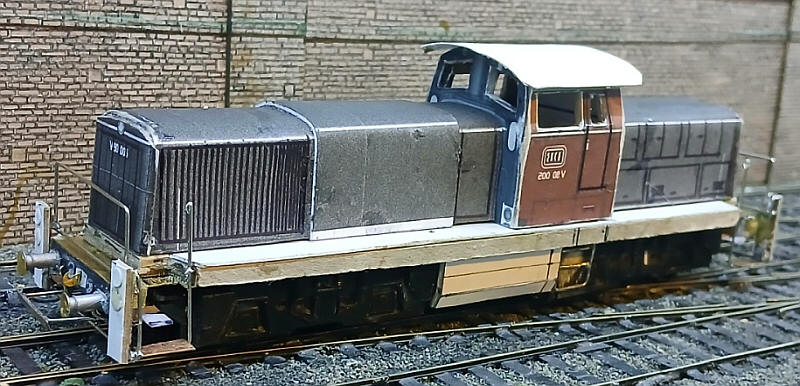
The locomotive's body has now been painted in DB Purporrot and transfers applied. At this stage the brass roof, with micostrip plastic rain strips fastened with superglue is loose and will not be fixed permamently until after the windows have been added. The transfers have been specially made for me by Modellbahn Decals.
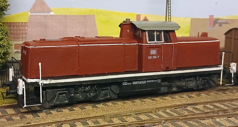
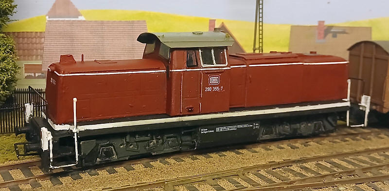
The completed model after about three months' intermittent work.
The model runs smoothly and is capable of slow running whilst haulage is more than adequate for the size of trains I am ever likely to run