DB Kleinlok
Once a common sight at stations all over Germany the Kleinloks or as they were also known Köfs.
The inspiration for the model was a card kit in pdf format by Albrecht Pirling who has produced one in 1:38 scale. In actual fact relatively little of the kit, apart from the cab, has been used as intended but the basic dimensions of the kit have been adapted for use to produce an operational S Scale model.
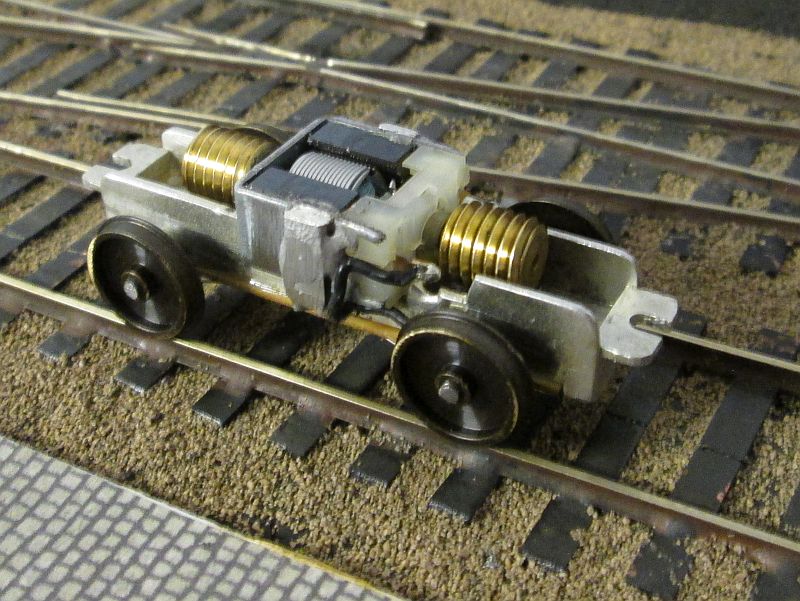
Construction started with a slight modification to one of the BEC tramcar power units that I am using for my German locos. The motor securing bracket was removed from above the motor and low melt solder was used to fasten the sides of the bracket to the melt frame of the motor.
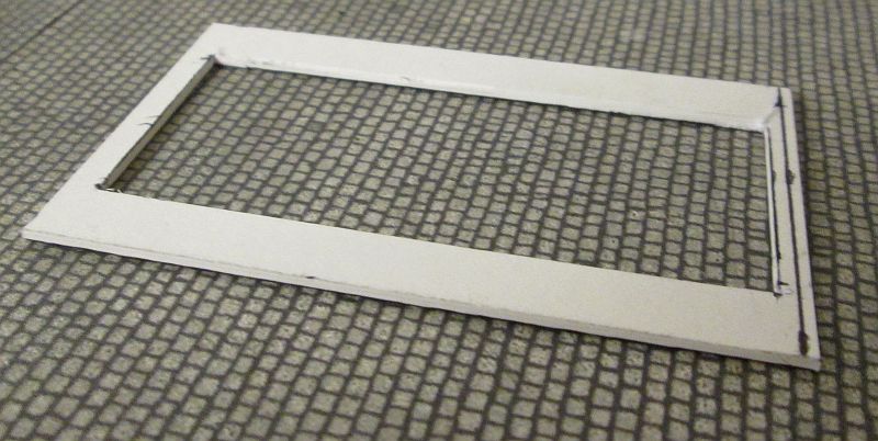
Construction started by cutting a piece of 1mm thick mounting card onto which all other parts will be assembled. Pieces of card were glued underneath it ...
....so that the card would sit at the correct height when fastened to the brackets at the end of the motor bogie.
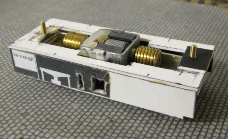
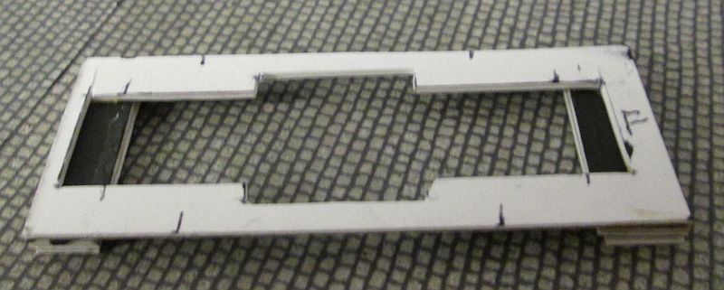
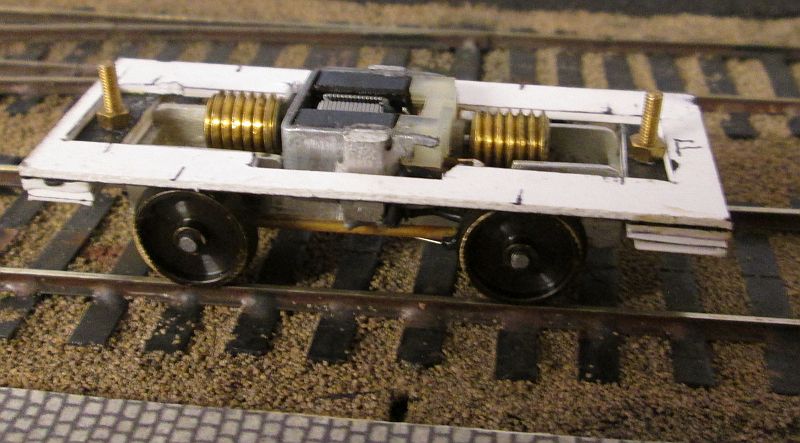
The securing nuts were held in place so they couldn't rotate with epoxy resin and small pieces of card. In this view the vertical side frames have been added and access holes cut out roughly.
The next stage was to cut another piece of mounting card to form the running plate used by shunting staff.
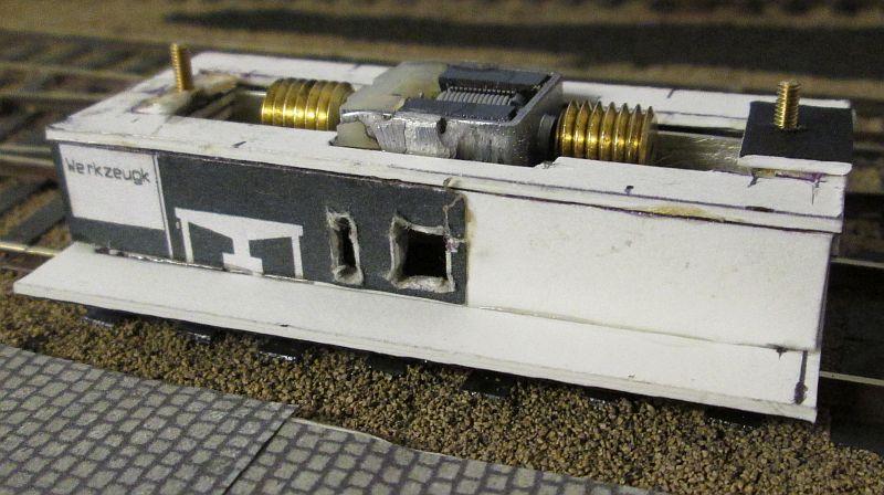
This was glued to the side frames....
...and as can be seen wraps right around the motor bogie. The bogie can be removed by simply unscrewing the bolts.
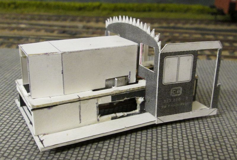
In this photo the cab has been cut out from the pdf kit and the motor bonnet is loosely in place. One of the problems with using the BEC motor bogie is that the motor securing bracket is wide than the width of the bonnet so I've had to cut a slot in the side of the bonnet. This will eventually be disguised by the bonnet doors. I've also turned the whole card base around through 180 degrees as for it was easier to fit the motor bogie inside the frames this way. The two small holes have been opened out and will eventually be covered with a thin layer of card with the correct size of openings.
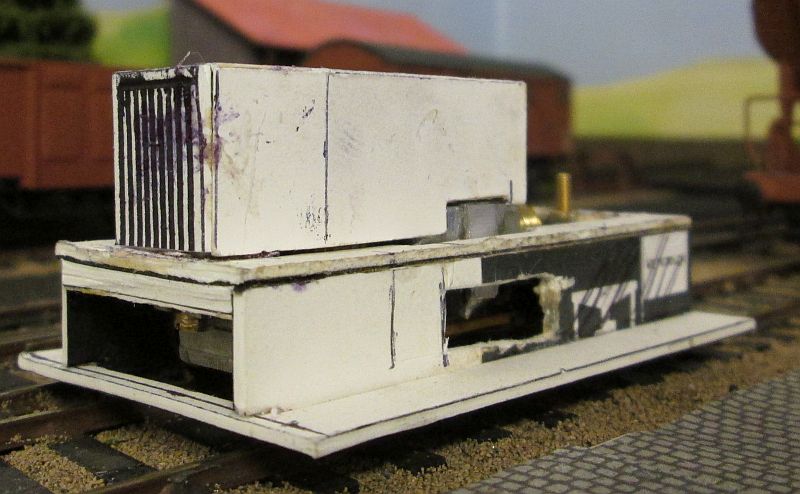
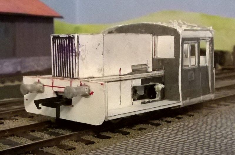
The basic bonnet has had a representation of the radiator attached and has been strengthened with thick card inside and weighted with lead sheet.
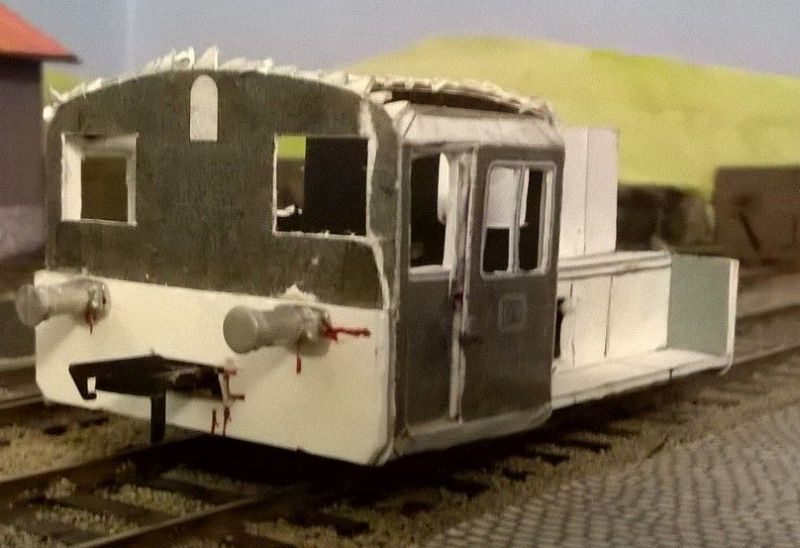
The cab sides and front (a one piece element on the kit's pdf) is now in place. An extra layer of card has been added to make the window frame as described for the 6 wheeled carriages. The cab door is recessed and because cutting this makes the cab sides very flimsy I've added extra strips of card and metal behind it to give a little more strength.
The cab rear wall has been added and the buffer beam. Something is wrong!
It was immediately apparent that the buffers would be in the wrong position so I removed the power unit and added packing pieces to make the model sit about 2mm higher,
I also decided to alter the bufferbeam position slightly so removed the original one, cut a piece of mounting cut to the correct shape and mounted it a little closer to the bottom od the cab windows.
Bachmann couplings were then added at the correct height by cutting a slot in the rear bufferbeam and securing them with epoxy. Holes were drilled for the buffers and glued in place with epoxy.
A similar method was adopted at the front but this time the coupling was held in place by the bolt that secures the power unit to the body.
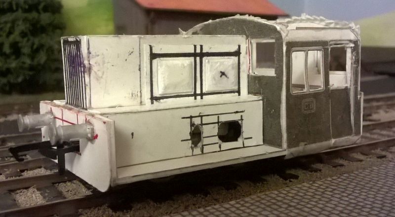
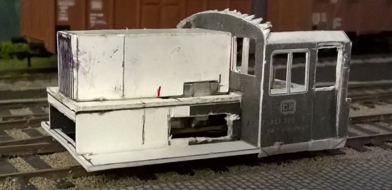
The next stage was to add some of the more cosmetic details such as the engine compartment doors. The raised panelling was formed by filing rectangles of card along each edge to produce the domed effect. More strips of thin card had access holes cut in them and were glued to the sides of the shunter's platform.
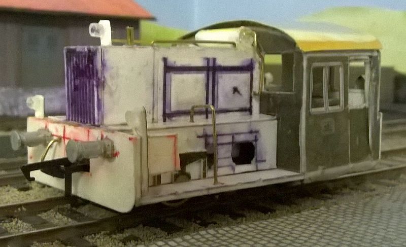
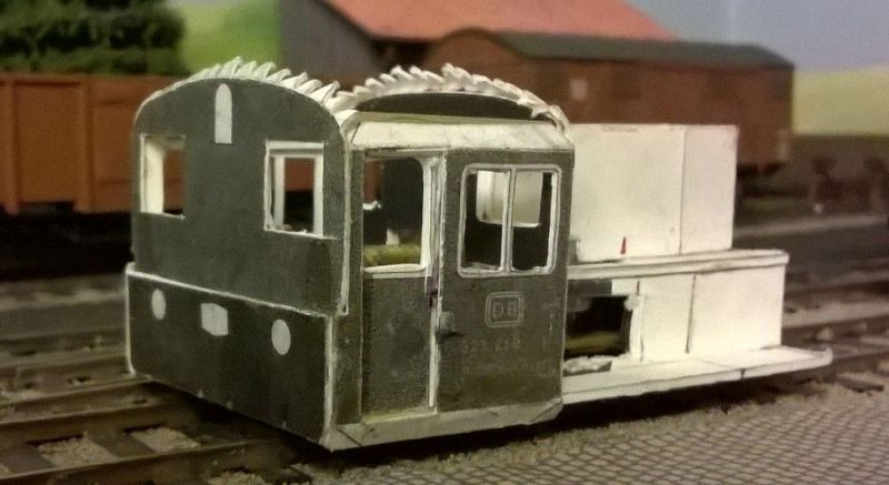
Most of the detailing of the model has now taken place and there is a brass roof which has been cut to shape and roughly curved to the required profile. This will be secured properly after painting and glazing. The two views show:
the headlights which are short lengths of plastic tube from old ball point pens.
The toolboxes
the numerous handrails for the shunter
The air tank and its feeder pipes on top of the engine compartment.
All the cardboard has now been treated with wood hardener (used for treating rotten wood).
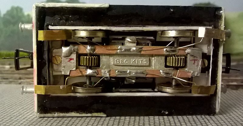
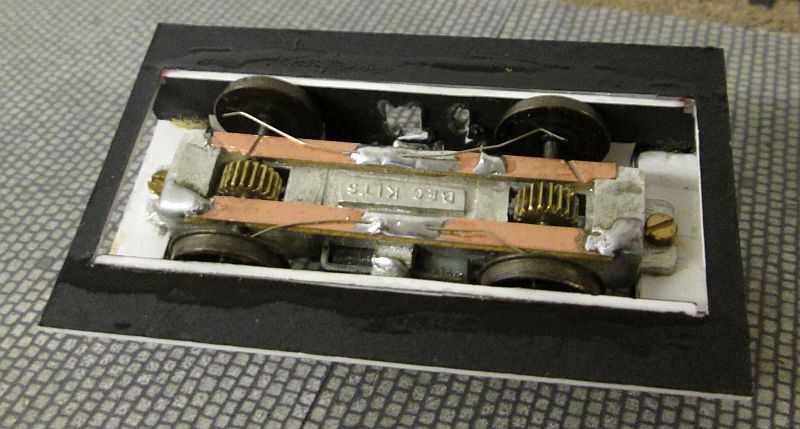
Being a four wheel locomotive electrical pickup is not of the best so I decided to use a system that I'd read about elsewhere. In each corner of the chassis I fitted what are probably best described as pickup skates. Short lengths of brass wire were soldered to the copperclad strips as shown above. The wires were bent so that they ended in line with the wheel treads and strips of thin brass soldered onto the wires. Each end of the brass strip was bent slightly upwards so that they will ride over point blades and check rails without getting snagged. The skates are adjusted for height by bending the wires so that there is sufficient pressure to keep them in contact with the rail head.
Performance is transformed with m much smoother running, although I feel a little more weight can be added in the loco's body to make things even better.
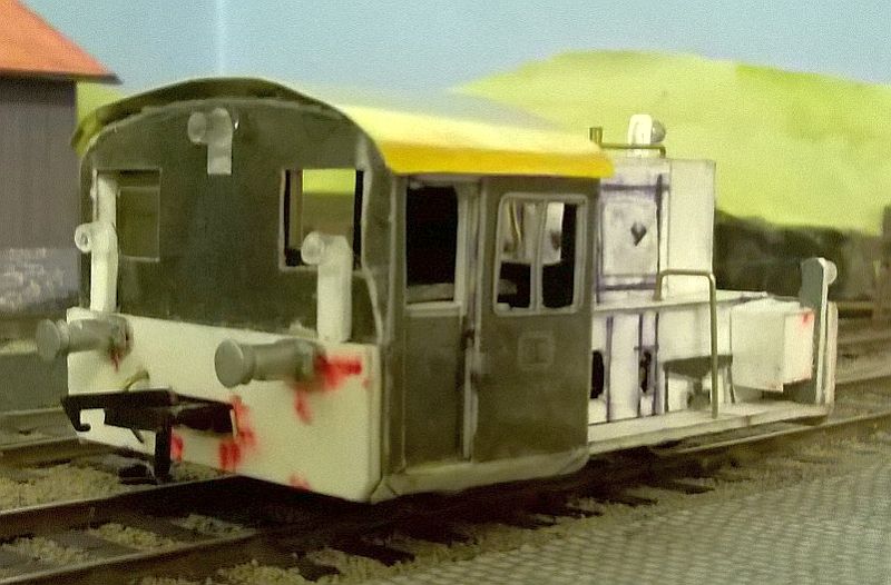
I've now added the cab roof ventilator and horns to the cab roof. To make this I first drilled a hole in the cab roof and solder a dress making pin in place. After cutting this to a short length (about 4mm) I thin added a short length of 5mm diameter plastic tube in place with epoxy resin. The pin acts as a location point and also strengthens the joint if the tube to the brass roof. Two short lengths of the same sort of pins were then glued into holes drilled in the sides of the tube.
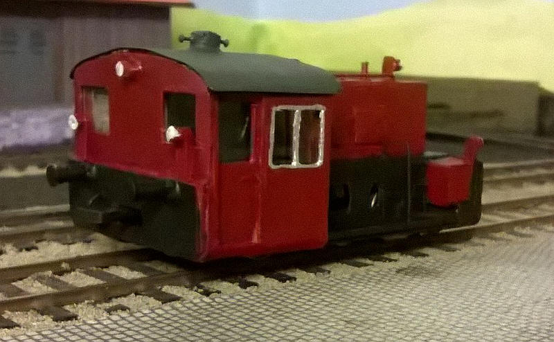
The roof has now been fixed in place and white dots painted on the headlights. One of them needs the red paint touching up!
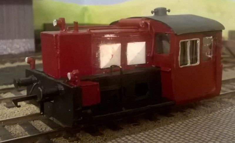
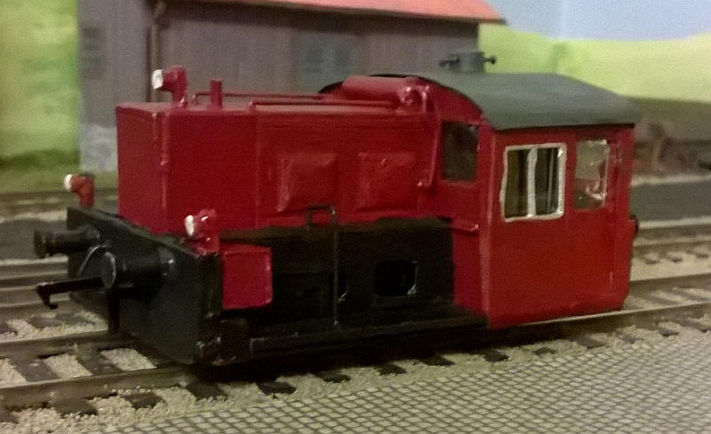
What became obvious once the model was painted was that the pyramid like panels on the engine compartment doors looked terrible. I had made them by filing pieces of card to shape and it hadn't worked as the card looked very rough. I decided to remove them very carefully with a knife and replace them with plastic filed to shape as I did for the doors of the 4-wheel open wagons
I cut rectangles of 40 thou plasticard 10mm x 10mm. I then drew diagonal lines on each rectangle and then using a file at a gentle angle filed along the edges to make a sloping edge. I then altered the angle and filed towards the centre thus removing some of the diagonal lines. I did the same for each side of the rectangles until the slightly domed shape that the doors show was formed. Each one is a matter of a minute or so. Then the plastic was stuck onto the sides of the engine room. After allowing the solvent to dry I scored two diagonal lines across each of the four panels to emphasise the shape.
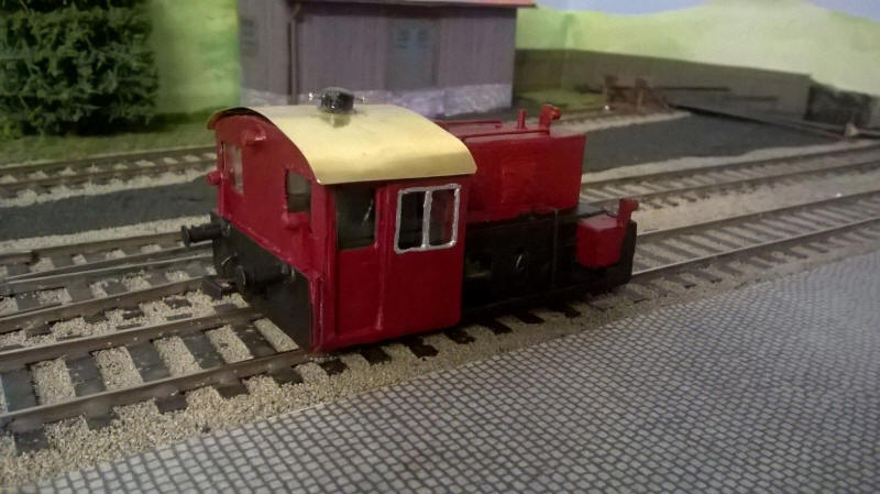
The model now awaits a repainting.
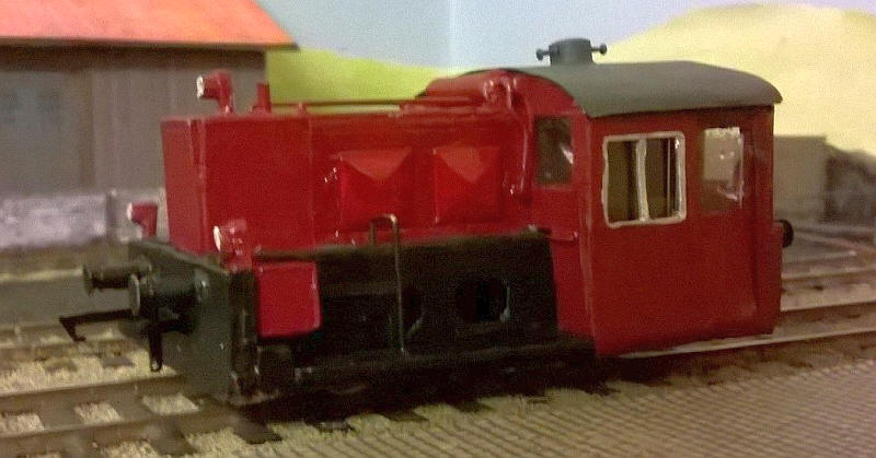
This looks much better. The model now awaits the decals I have on order.
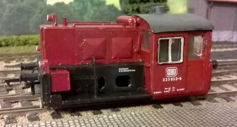
The model is now complete with transfers - a mixture from Modellbahn Decals and British produced transfers (for the numbers).
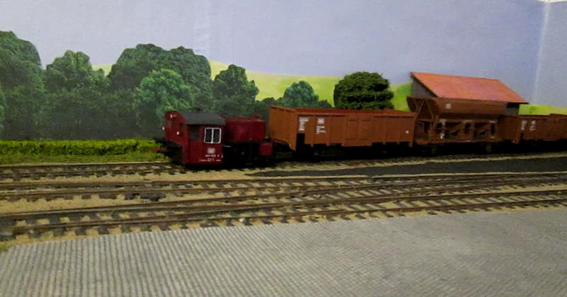
Click on the photograph above to see a film of the Kleinlok in action.