MR 700 Class 4-4-0
On this website I've described several locomotives that have been scratchbuilt but I haven't written about building one of the many models built from the kits manufactured by Alan Gibson. Sadly it seems that these are no longer available to buy unless multiple kits are ordered.
I was fortunate to be able to purchase most of Alan Gibson's S Scale kits when he sold his business and many of these are illustrated on this page:
https://www.steverabone.com/sscalewebsite/midland_railway_loco_portraits.html
I've now reached the stage when I have built almost all the kits so I've decided to document this final model which is a 700 lass 4-4-0 fitted with a large Deeley tender.
Whilst I have almost all the parts needed to build the model - brass and nickel silver etches and white metal castings there are a few items that are missing and I will have to improvise.
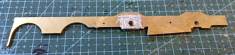
The first problem was that whilst most of the models had frames with just a small pilot hole for the driving axles the 700 frames were different. The front axle had a square hole which was intended to use a sprung hormblock. As I didn't want to introduce this level of complexity I decided to solder a nickel silver hornblock blanking plate and mount the top hat bearing in the hole in the plate. In order to get the axle holes in the correct place after soldering the plates into the frames I soldered the frames together ensuring that the pilot holes for the brake rods and rear axle were exactly aligned. Then the two top hat bearings were aligned with a spare axle rod and the bearings soldered in place.
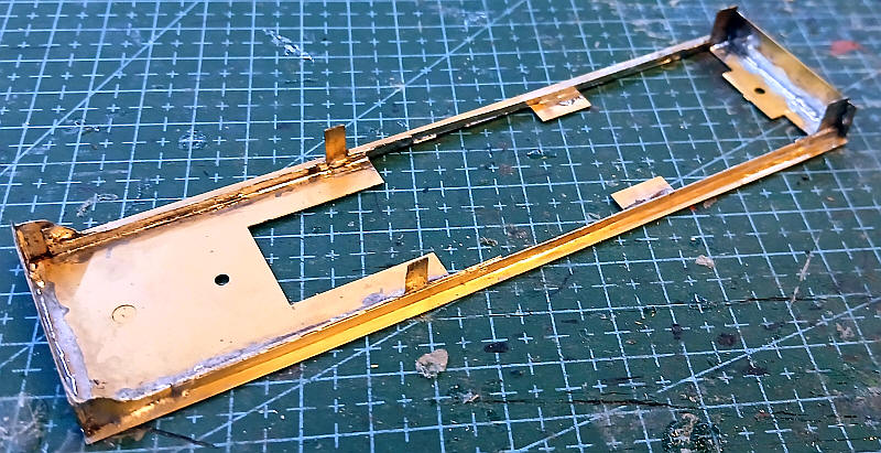
The next problem was that there were no nickel silver parts for the footplate valances. What I did have was a pair of valances for a Midland 2P 4-4-0 which, of course, have a raised centre section. I cut off the front and rear section of the valances and soldered them in place to the underside of the brass footplate. This gave me the support brackets for the four steps at the cab end and in the middle of the locomotive. I then soldered nickel silver strip along the underside of the footplate securing it to the two sections of the 2P valances. There was a short section at the front bufferbean where a piece of bass was cut to shape to form the curved section of the valance at that end. Finally the cab end drag bar and the front bufferbeam were soldered in place. To my surprise the frames fit exactly between the buffer bean and the drag bar.
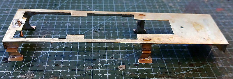
I've now added the various footsteps. The 700 class kit had alternatives so I chose the correct ones for the locos numbered after 710. The step back plates were soldered to the extension pieces of the valances, a job that wasn't easy as holding them in exactly the correct place whilst soldering proved tricky. The rear of the backplate was strengthened with a length of brass wire. The steps were folded up and soldered into the locating recesses. A 10BA nut was soldered in place on top of the frames at the cab end and a 10BA bolt was soldered into a recess on the underside of the footplate just behind the bufferbeam. These will be the locating points for two of the frame spacers.
The frames have been assembled using the frame spacers included on the chassis etch. The bogie has been assembled as a rigid bogie rather than one where the frame sides can rock. This meant soldering the two parts for each bogie side together and then soldering washers on the top of the bearing holes.
I cut a small piece of brass sheet about 18mm by 12mm to act as the bogie stretcher. This was scored at the outer ends and bent into a U shape and soldered in between the bogie frames. A hole was cut through the stretcher to act as a pivot point for the bolt passed through one of the main frame spacers. To ensure that the bogie would cope with the layout's sharp curves I deliberately made the bogie stretcher quite narrow; about 14mm - this allows a lot of horizontal movement of the axles to take place.
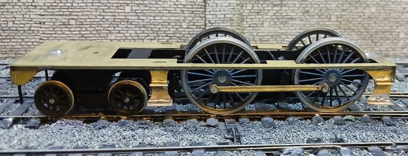
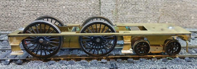
The chassis has had its brakes fitted and has been painted. The permament driving wheels have been fitted together with the coupling rods. The chassis rolls freely although one of the wheels has a slight wobble to it - I find Gibson wheels difficult to fit as they rely too much on getting the axle through the central hole absolutely square.
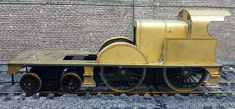
The cab, firebox and front wheel splashers have all been folded up and soldered onto the footplate. The etches are generally very accurate although a few places needed attention with a file to fit properly.
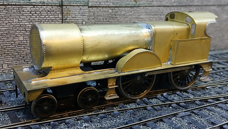
The boiler and smokebox assembly are now in place and the frame extensions around the smokebox have been added. For some unknown reason there is no etching for the front of the smokebox so i have soldered a thin sheet of brass to the end of the tube and cut and filed it to shape.
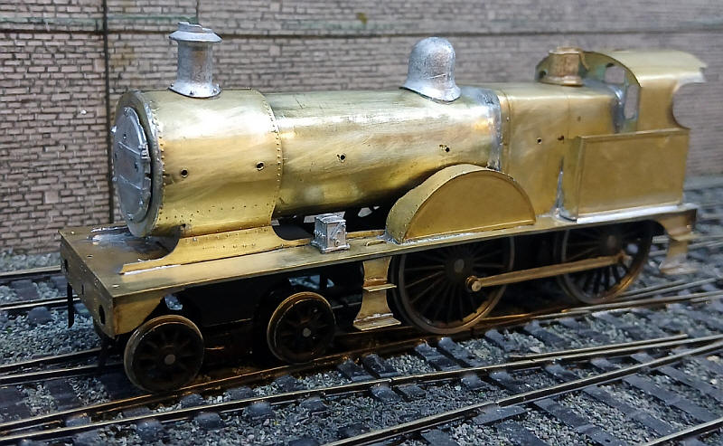
The various castings for the boiler have been fitted and the holes for handrail knobs drilled.
I've now largely completed the "heavy" work on the loco. The Deeley tender has been constructed more or less as intended with the exception of the chassis.
Rather than use the normal frame sides for the chassis I'm following one of my preferred methods of powering the loco by using the tender drive unit from an old Airfix "Royal Scot" which I had obtained cheaply through Ebay. The disadvantage of this is that for the older Johnson type tenders the wheelbase is almost spot on but for the longer Deeley tenders the wheelbase is too short by about 5mm. Once the wheels are painted and the loco is running on the layout I will barely be aware of this descrepancy. My MR Compound has been running around the layout for years with this issue and it has never bothered me!
An explanation of the method of using "Royal Scot" under S Scale loco tenders can be found here.
https://www.steverabone.com/sscalewebsite/tender_.htm
To give access to the securing screws holding the drive unit to the tender superstructure it is necessary for the tender top to be removable.
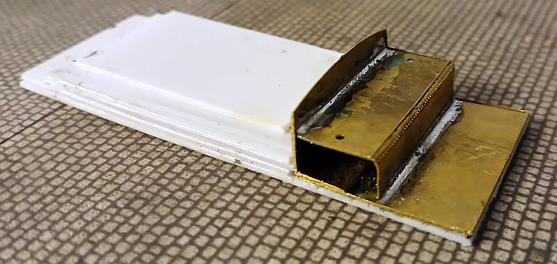
A base of 1mm thick plastic was cut to fit inside the top of the tender. It is supported on plastic strips glued inside the tender body along the sides and rear end. A hole was cut in the base to allow clearance for the top of the motor.
The brass parts for the rear of the tender top were reduced in width slightly to allow them to slot in place between the tender sides. Strips of plastic were added around the hole in the base up to the level of the top of the motor and then a smaller rectangle of plastic was glued over the hole. Eventually all the plastic will be painted black and coal added.
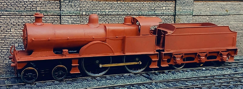
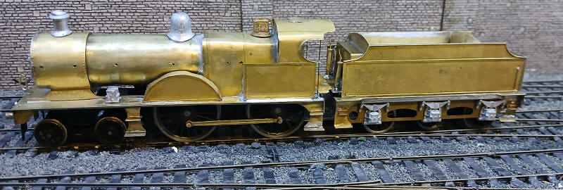
The model is now virtually complete apart from painting and adding the buffer heads.
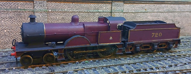
The finished model ready to join the rest of Halifax's express loco fleet.