The new German S Scale layout
Having built two locomotives and a rake of carriages I clearly needed a layout but where to put it was a problem. The only space in my library/ railway room is above Halifax Midland. This would allow a baseboard 8' 6" by 1' 5". That was enough to build a small three road terminus with lines just long enough for a four coach passenger (6 wheel type) or about 5 or 6 freight wagons. Obviously, there was no space for a fiddle yard so the plans stalled until I realised that I could link the new station to the Pendle Midland layout and use the Pendle Midland fiddle track for the German trains.
German railways use flat-bottomed rail and as I had a large quantity of used Peco code 100 track I decided to build the layout using the rails from old Peco Code 100 points and flexible track soldered to paxolin copperclad sleeper strip. This meant that I wouldn't have to do any heavy filing of rails, something which I don't like doing nowadays with my hand problems. Basically, the method for converting the points follows these stages. I used the large radius and the curved points which allows radii of between 36 and 60 inches to be formed.
The main stages in producing the S Scale points
Using side cutters snip the plastic sleepers on either side of the crossing V (frog), the closure rails and the point blades so that the outer stock rails can be removed.
You are now left with a unit made up out of the crossing V (frog), the closure rails and the point blades. I usually unclip the point blades from the closure rails at this stage.
Remove the sleepers from the crossing V rails a few at a time and replace a couple with copper clad sleepers to maintain the alignment of the rails.
Repeat this for the closure rails but at this stage don't disturb the actual crossing as these have moulded plastic inserts and we want to keep these as far as possible to ensure correct alignment through the crossing.
Turn this unit upside down and remove the plastic under the crossing by cutting away with a razor saw and file. You will be left with a thin layer of plastic around the base of the rails. This will be useful to retain for later on. Copper clad sleepers can now be soldered to the outside of these rails .
If using the large radius point I now refit the point blades and start soldering the stock rails to the sleepers and the crossing end of the point. You need to ensure that the point blades fit into the recesses on the stock rail. At this stage I also lay the partially completed point on a diagram marked out for sleepers at the correct spacing. I use double sided sellotape to hold the sleepers in place.
Construction now follows the normal process for constructing point with the straight stock rail laid first, followed by the curved stock rail. You'll need to make some adjustments to the alignment of the curved closure rail to ensure that the rails all line up correctly and a 48 inch radius curve is maintained through the point. This is easier to do than to explain.
The point blades can be fixed to the closure rails using either the special fishplates from the original Peco point or just by using normal fishplates - there will be sufficient freedom of movement using these.
The tiebar uses a strip of sleeper strip.
Check rails are soldered in placing opposite the crossing and the point checked for running using a wagon. The closure rails are gapped as for any live fog point and then gaps are cut in the copper of the sleepers.
The entire process takes less than an hour to produce a point that is suitable for S scale using wheels of the EM Gauge profile by Alan Gibson or Jackson coach and wagon wheels.
If using the curved points that Peco make you will need to insert an extra length of rail about 40mm to extend the closure rails. This is so that a minimum radius of 36 inches can be maintained on the inner curved line. Obviously the outer stock rails will also need extending at the crossing end by the same amount.
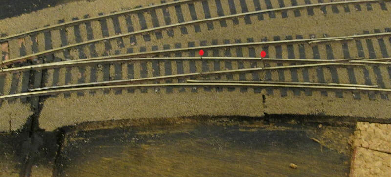
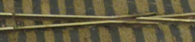
The photo shows one of the curved points after ballasting. As mentioned above the closure rails will be too short as the gauge has been widened by about 6 mm. A new section of rail will be need to be inserted between the blades and the closure rail. This can be seen in the photo above marked by the red dots. Some carefully measuring is necessary to ensure that the radius of the curved line is consistent and also that the point blades line up correctly with the recesses in the stock rail. The stock rail will also need to be lengthened at the crossing end as a result of this. It's much easier to do than to describe and each point actually only took about an hour to convert. Both Peco curved and long radius points were used on the layout giving minimum radii of either about 36" or 48"
At the actual crossing V the underside of the plastic was cut and filed away so as to be level with the underside of the rail and more sleepers soldered in place. Doing this means that the entire crossing remains undisturbed and alignment is guaranteed. This unit was then fastened (using double sided sellotape) to the point template that I'd drawn and all the remaining sleepers were put in place.
The photographs below show progress on the construction of the layout.
The track to the new layout joins on to the goods run round line at Pendle Midland .
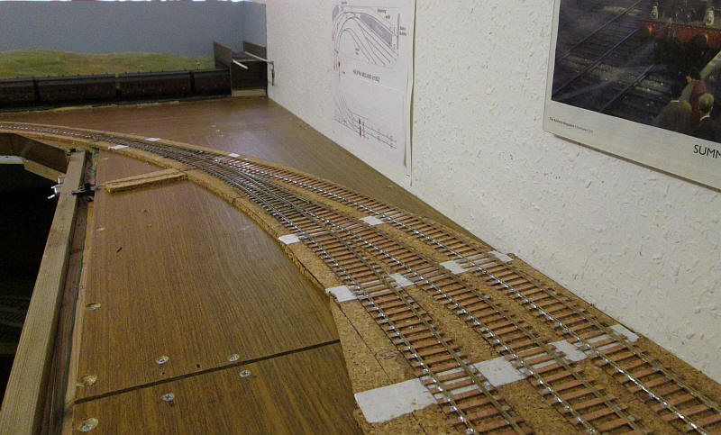
The approach curve's radius is 36 inches which most of my locomotives and rolling stock are happy with. The approach line splits into three using converted Peco curved points with an inner radius of 36 inches and an out one of 60 inches. The white strips under the track cover the gaps in the cork underlay. This is cut from cheap table mats.
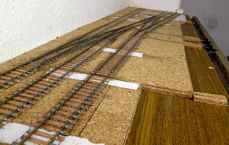
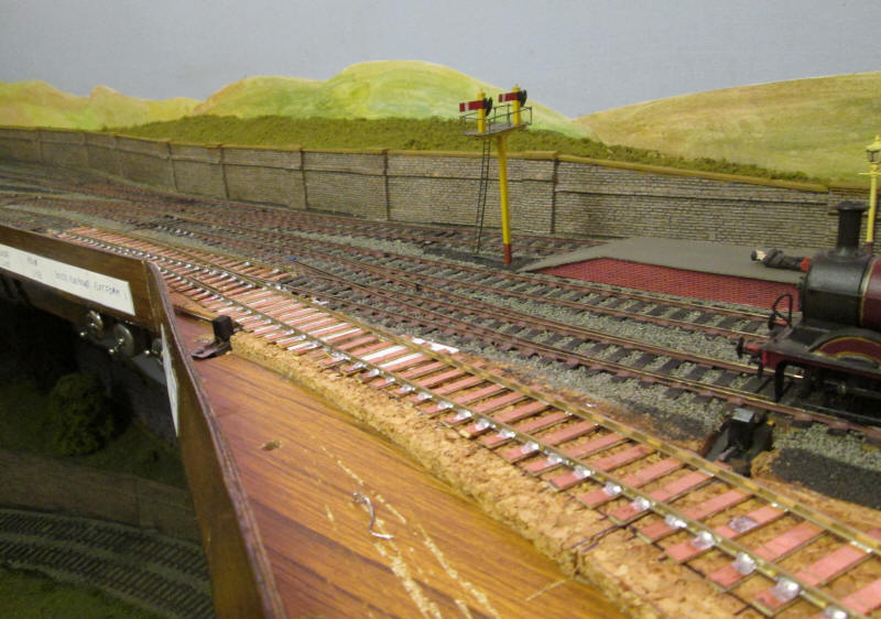
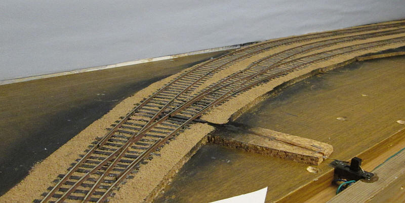
Looking the other way the three loop lines split into three dead end lines - the two outer ones will be freight sidings and the centre one is the locomotive release line.
This track layout is quite typical of many small German branch lines.
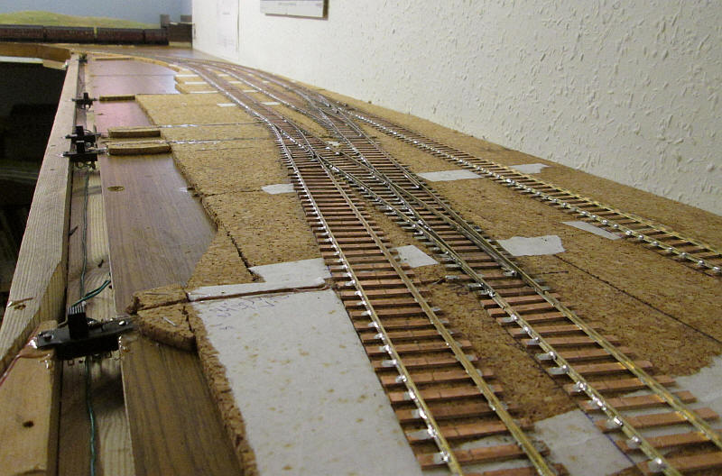
Looking from the end of the layout the three points in view were converted from Peco large radius points and have an inner radius of 48 inches.
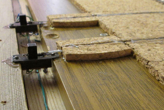
Points are operated by wire in the plastic tube method. The main baseboard uses an old piece of bookshelf - half inch chipboard faced with melamine which then has two pieces of 50mm by 20mm timber screwed to it to make this channel. This gives space for all wiring to be contained in the channel. Short lengths of brass tube are soldered to the wires passing through the switch sliders and are soldered in the correct position to limit the movement of the point operating wire.
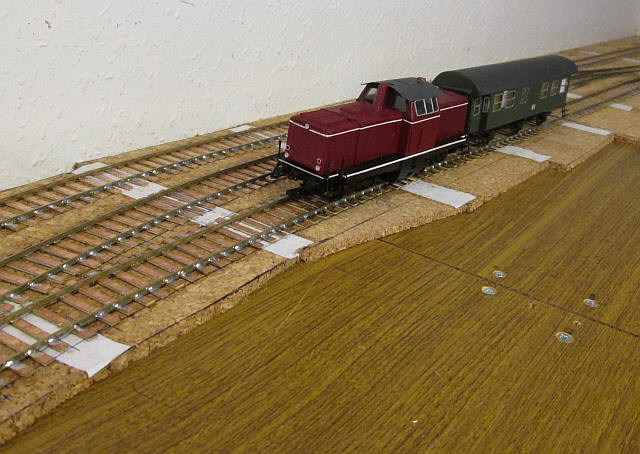
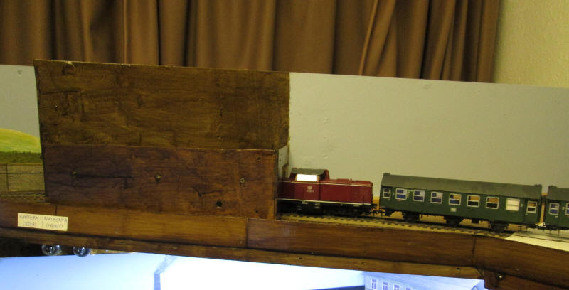
The first German train on the layout is the centre cab diesel and the first of four 6 wheel coaches that are under construction. Train lengths will be short; passenger trains can be of four 6 wheelers or three short bogie coaches. This was the typical German branch line train in the 1970s and 1980s. freight trains will be about 5 or 6 vehicles long.
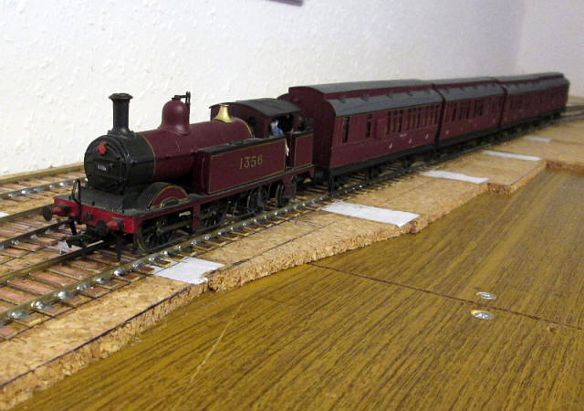
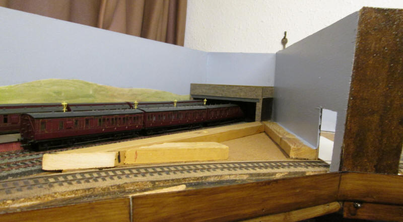
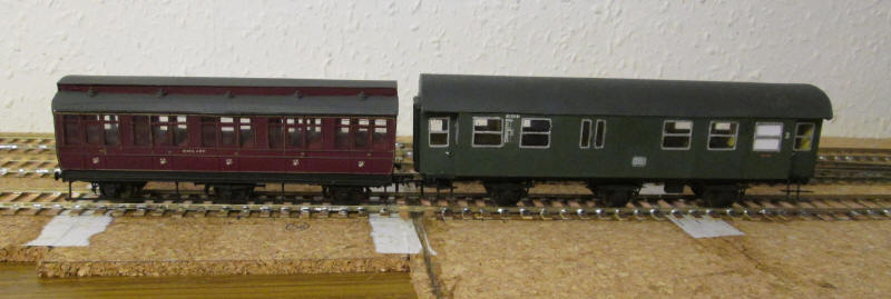
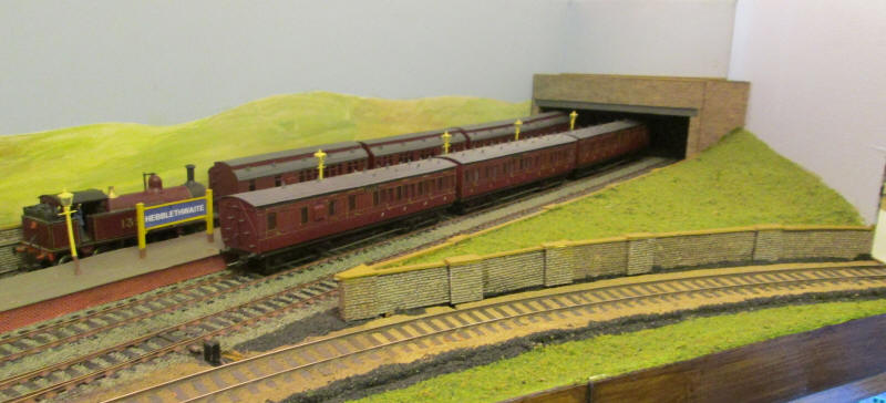
I couldn't resist running a Midland train onto the layout and what is immediately obvious is how much more spacious this new layout looks with the smaller pre-grouping British stock than German.
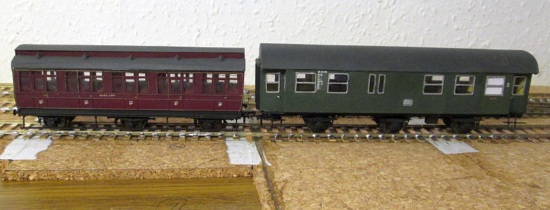
Nothing really needs to be said about the relative sizes of these two S Scale vehicles - look at the differences in height between the two models.
Separating Pendle Midland from the German layout will be crucial and the method I've adopted is to have two removable back scene boards attached to triangular bases on which scenery appropriate to either the German or British layouts.
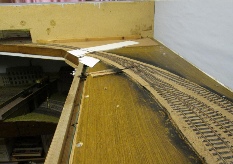
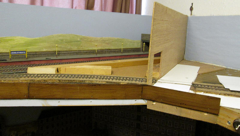
In the photo above the white area will eventually be a road over a level crossing. Beyond that is the "German back scene" which slots into place next to the road. This effectively cuts off the German layout visually from the British one.
To hide the large hole on the left hand side of the "German" back scene I decided that the best way to conceal this would be by building a plywood box which is fastened to the chipboard back scene board and painted with the same oak coloured varnish as the edges of the layout.
When I want to operate Pendle Midland this back scene board be used and will butt up to the road. To the left of the board and fastened to it is another triangle of plywood onto which "British scenery" will be built. In the same way that Pendle Midland will be the fiddle yard for the German layout, so British trains could also run down this "freight only" branch onto the German layout and use it as a fiddle yard. My 0-6-0 locos all cope happily with the sharp curves and points.
The photo above shows the "British" back scene board in place with the varnished end piece which strengthens the plywood and also acts as a sort of frame to separate Lancashire from Germany.
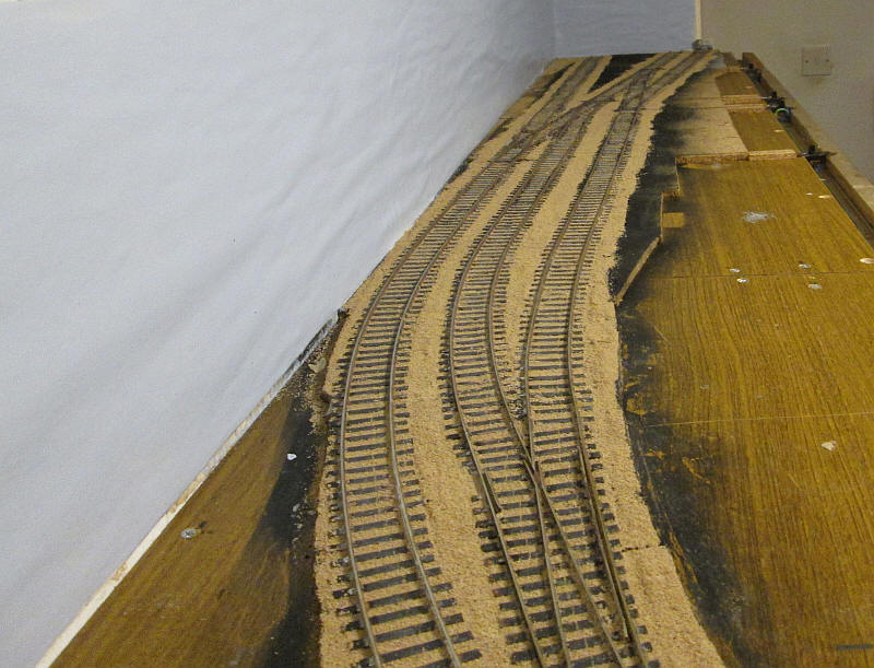
The completed trackwork was ballasted with Woodlands Scenics N scale ballast which is a suitable light colour and was then weathered with washes. The photo shows it somewhat brighter than in reality. The ballast was applied by painting undiluted PVA around the sleepers and scattering the ballast onto it. This was then sprayed with water and dilute PVA dribbled onto the ballast from an ear dropper bottle. A little tidying up is necessary after the adhesive has dried but it produces a very securely fixed ballast.
Obviously, German rolling stock is higher and wider than British ones. I'm only having to alter one structure on Pendle Midland to allow the German stock to run on it: the bridge has been lifted up by about 5mm to give sufficient clearance.
The "British" back scene board has now moved on a bit with the basic scenery or retaining walls and grass cover. The joint between the removable board and the fixed layout is almost invisible.
Buildings for the German layout
I've decided that rolling stock construction for the German layout probably needs to be put on the 'back burner' until the basic scenery and structures are completed.
Obtaining measurements to scratch build German buildings is an obvious problem but there are dozens of free building kits available as pdfs on the internet. A search for 'Kartonmodellbau Gebaude'
reveals that almost any type of railway, domestic or civic building is available and in many regional styles. Many happy hours were spent searching for and downloading these documents!
The concept of the layout is that the branch serves a typical Bavarian country town. Now Bavarian does not have to mean mountains as most of that region comprises of rolling countryside.
Station buildings
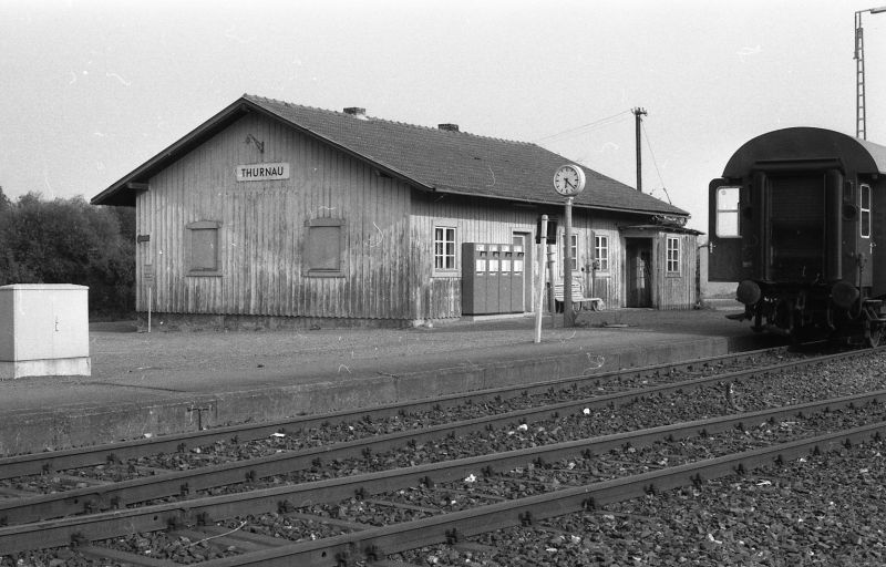
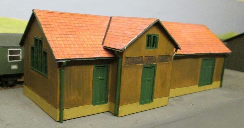
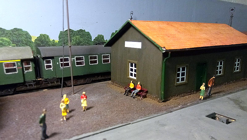
Thurnau station building was a small timber structure which I have compressed to produce ...
.... this small structure. It's considerably shorter and narrower as space is tight. The model is built from thick mounting card scribed with a biro to given the impression of lap-boarding. The pantile roof is from the Scale Scenes downloadable pdfs (paid for!).
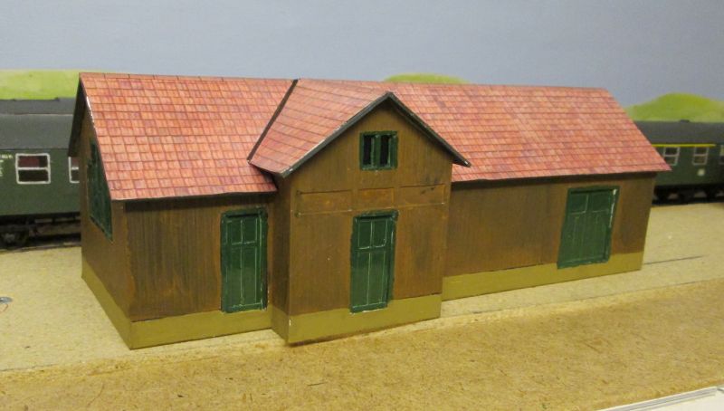
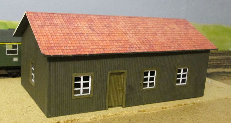
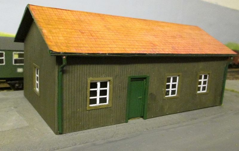
The goods shed is a downloadable model from the www.gtp.de website of that at Endingen in Baden-Württemberg. I used the HO version modified to give a structure about the right size for S Scale.
Neither the station building nor the goods shed are completed yet as I have decided to build the basic structures first and then return to add details once all are complete. This means that overall progress to get a visually interesting layout will be faster than if I concentrated on one structure at a time.
The town
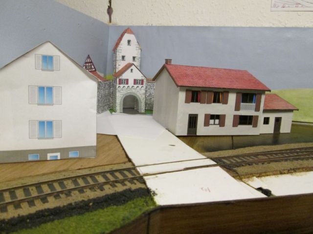
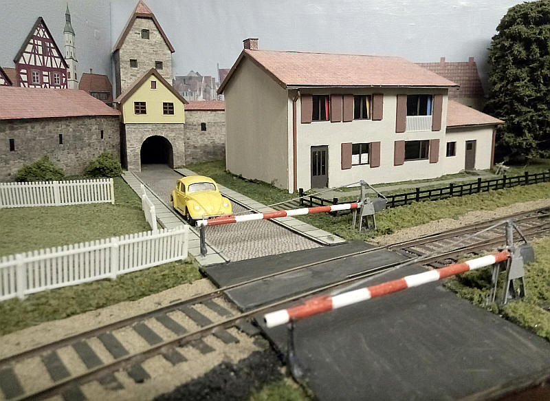
I needed a way of disguising a very obvious right angle corner where the removable board meets the fixed part of the layout. One feature of many small towns in this part of Germany is that there are often remnants of fortifications from the medieval period. So, the corner joint will be hidden by an arched gateway and a short remnant of the old town walls. The photos below shows how this is being planned.
 |
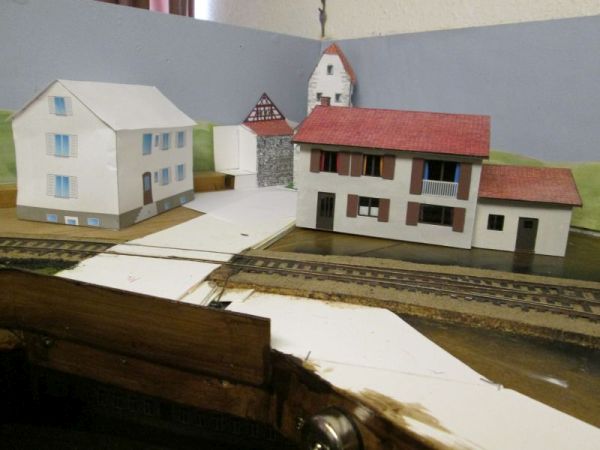 |
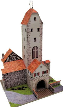
The road that crosses the railway leads to one of the town gates. On either side of the gate there will be sections of town walls, which in many German towns incorporate buildings. The structure shown in these photos is from a series of kits of structures based on buildings in Wangen in Allgau and are on the www.wediul.de website. I'm building these in a smaller scale - approx 1:87 to give a little forced perspective as if they were further away than a couple of inches.
I've used different parts of the kit printed out onto paper, cut and modified to suit the place on the layout, to produce a suitable structure to fill the corner.
The photo below shows the kit as designed.
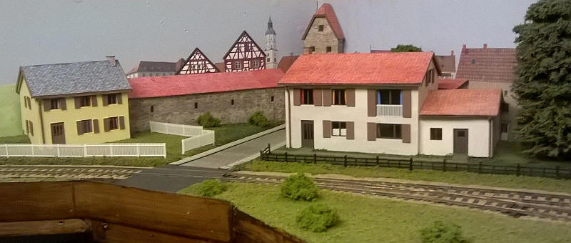
The other domestic buildings in the photos are typical post-war German houses that can be found all over the country and are shown in both the paper mock up form on the left and the largely finished model on the right.
A name for the layout - Niederwangen
Choosing a name for a fictitious layout is always difficult. I'm thinking that a suitable name would be Niederlangenau or Niederwangen given that several of the buildings on the backscene are from those two towns.
In the end I've decided on Niederwangen (pronounced Knee-der-vangen)
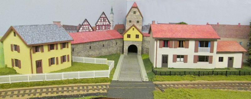
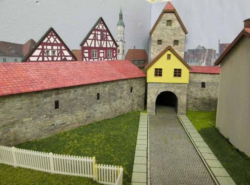
Two views of the partially completed townscape. The "buildings" behind the town walls are print outs from the Internet of real buildings or from the pdfs of various kits.
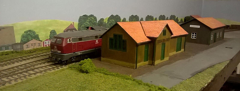
The goods shed has now received gutters and drainpipes as has...
...the station building
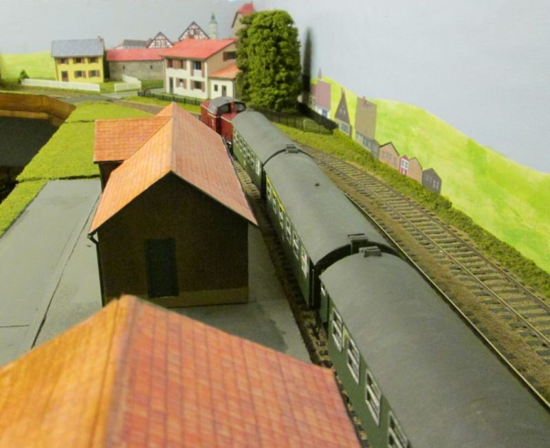
A view looking along the layout.
The station approach with BR211 ready to depart.
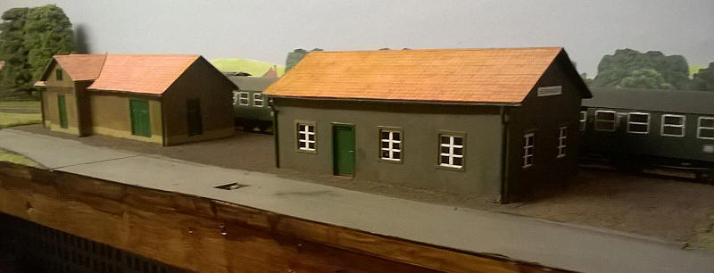
The station building and goods shed have now been bedded in with the platform surface.
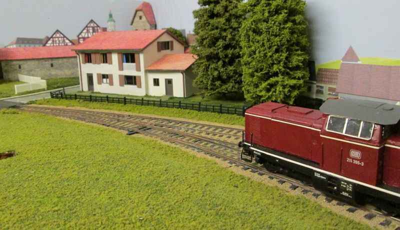
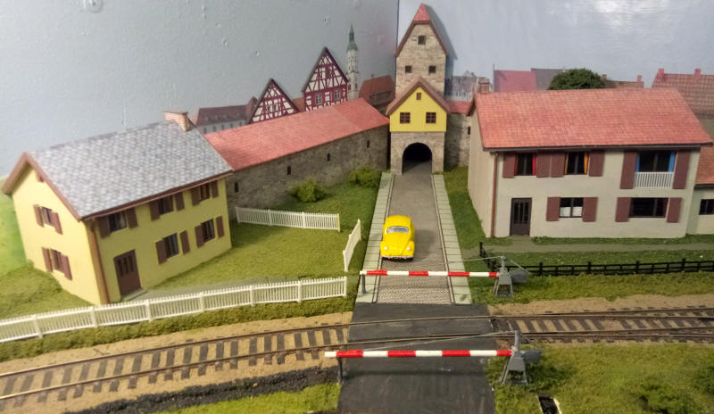
Looking along the station approach road.
The "open" level crossing and houses with garden fences.
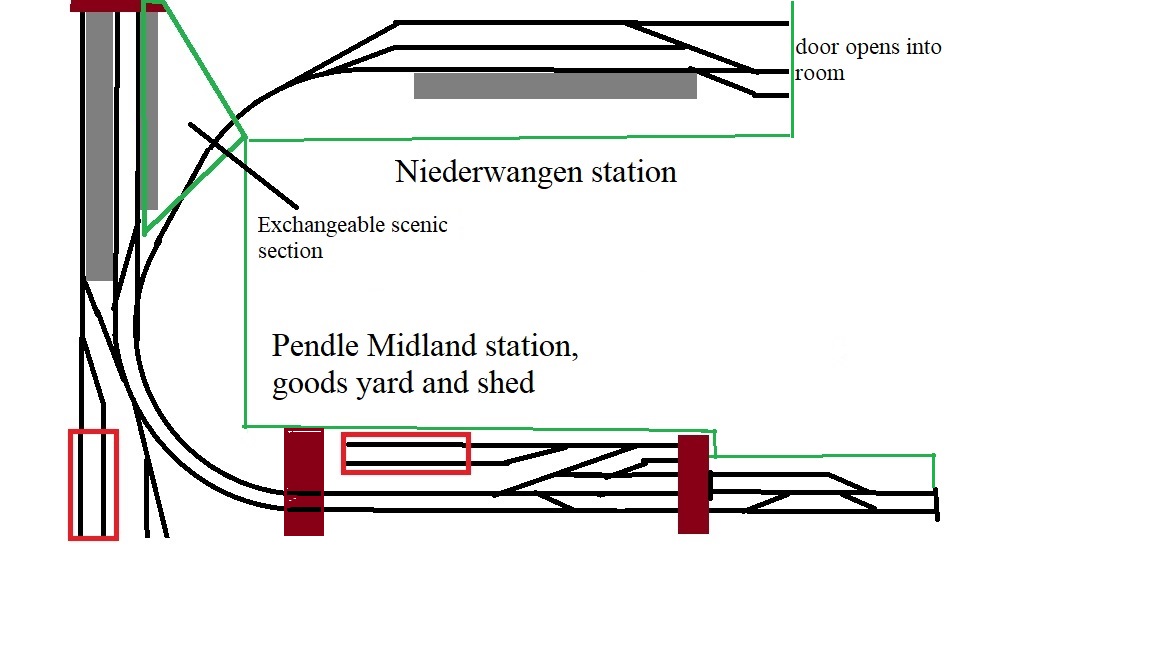
The German layout and how it links to Pendle Midland to act as a fiddle yard.
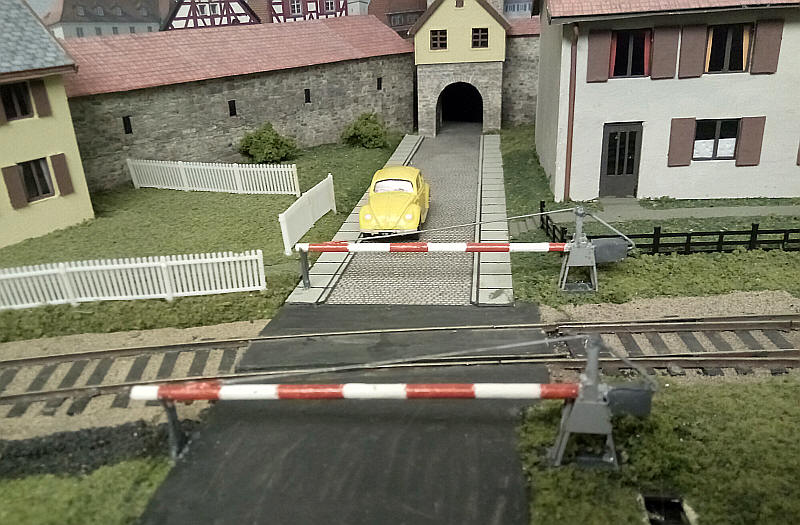
At last I have got around to making the level crossing barriers. They are fabricated out of a mixture of brass sheet, tube and wire, nickel silver rail and strip all soldered together to give an approximation of a typical old style crossing. The counterbalance weights are folded card attached to the barrier booms. I'll now need to make a crossing keeper's hut from which the barriers can be controlled, as well some of the X shaped crossing warning signs.
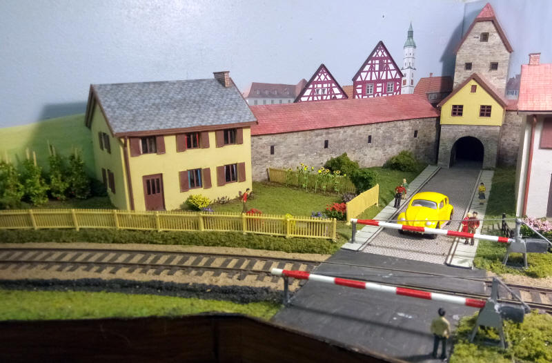
I've continued adding details - sunflowers and runner bean plants as well as......

.....lots of flowering bushes.
Some cheap 3D printed figures have been used to show a scene after the arrival of a train.
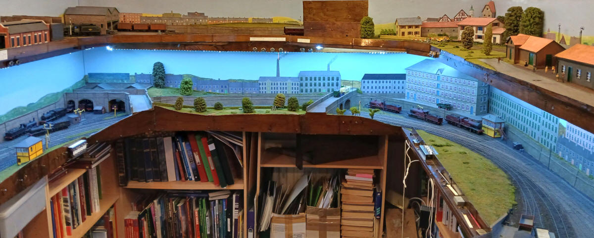
The photo above shows the positions of the three S Scale layouts. On the lower level is Halifax Midland whilst on the top level is Pendle Midland to the left and at the far end. Niederwanagen is on the right.
Building a Deutsche Bundespost bus
A common sight at many DB branch line stations was the Deutsche Bundespost or Deutsche Bundesbahn bus. I needed something to fill up the large empty space at the far end of the station. It's really a cobbled area for unloading freight wagons but it was often where buses could be found between trips.
There are numerous websites devoted to DBP and DB buses on the internet and I found some scale drawings of a Mercedes Benz O317 which was built from about 1967 onwards so would be suitable the end of steam and early diesel years
http://www.bahnbus-bildarchive.de
has lots of good photos
has excellent side elevations
I selected the Mercedes Benz O317 accepting that I would have to make compromises in the body shape due to the difficulty of building the model in card. The principal compromise is that the body side does not slope in at the top but remains vertical.

The side images were copied and cropped and resized to S Scale. A computer program was then used top insert a blank area where the roof will be. This was then printed out on card....
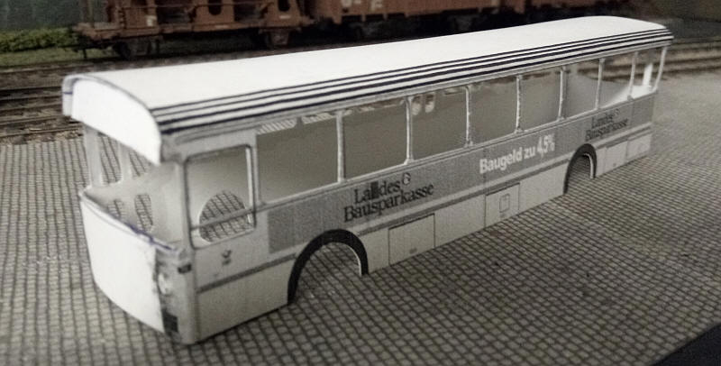
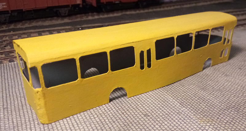
.....and the windows were very cut out. The roof edge was scored several times with a biro and the card then bent to give the basic body shell. Small pieces of card were added at the front and rear of the body and the card was given a couple of coats of pale yellow paint. The structure is of course extremely fragile.

To strengthen the body strips of 1mm clear plastic were glued inside the side window areas. Additional strengthening was added using thick mounting card under the roof and the lower body sides.
Glazing at the front an rear of the body uses small pieces of thin plastic glazing.
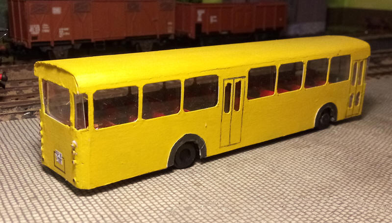
This is the almost complted model -it just needs a few roof ventilators adding. The interior is model on a floor base of mounting board with seats fabricated from strips of card. The base has to be cut into two to be inserted in the body and is held in place with furthur strips of mounting board and adhesive.
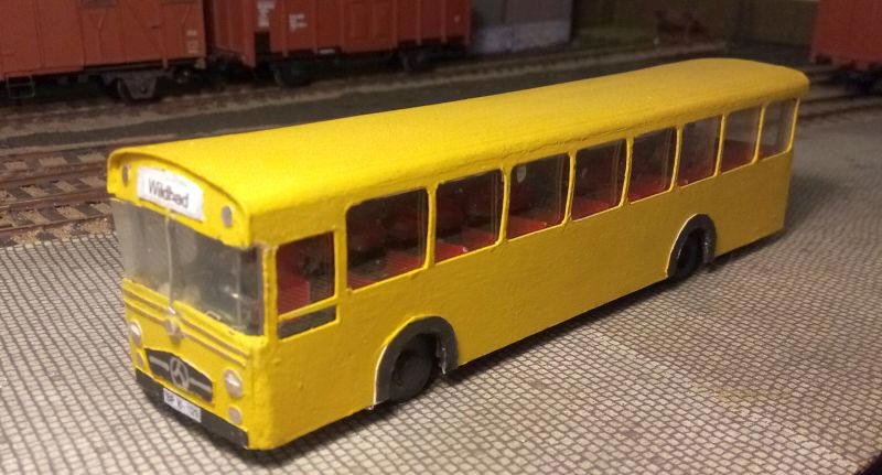
The steering wheel is a circle of nickel silver wire soldered to a steering column of brass wire. The wheels are very slightly to small but are based on steel washers with mounting card layers glued ot the washer and cut and filed to a circular shape. The windscreen divider is a 1mm wide strip of nickel silver etching. All the other details on the cab front are microstrip plastic or circles of card painted to represent headlights.
There are many faults with the model but it overall captures the feel of a late 1960s bus and gives a focus of interest on part of the layout that needed it.
Videos of the German layout
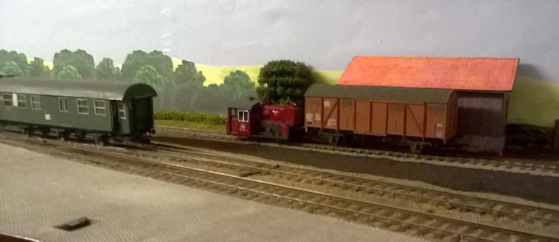
The Kleinlok shunter stands in front of the small goods store shed. Click on the photo to see a video of the locomotive running.
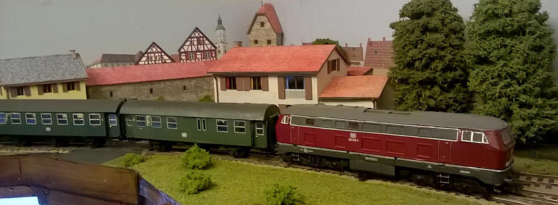
A Class 216 runs in on a passenger train. Click on the photo to see a video of the layout.