Building an Alan Gibson Patriot kits
A conversation with Alan Gibson revealed that he still had some of his LMS S Scale locomotive etchings in stock. I decided to order the Patriot and the Crab, as these had parallel boilers and Fowler tenders. This would ease construction as clearly the boilers could be constructed easily from tubing that Alan could supply whilst the tenders would allow me to use my tender drive method of propulsion should I decide against powering the loco.
The kit came with no instructions and obviously lacked a firebox as the original 4mm kit had a cast one. An enquiry on RMWeb resulted in two modellers sending me scanned pages for both of the kits; what a marvelous group of people modellers are to spend time helping stranger out!
The new owners of Alan Gibson kindly dug out all the wheels I'd need so I was now in the position to begin construction.
Constructional notes
I'm not going to give a blow by blow account of construction as I followed the instructions fairly closely, at least as far as the chassis is concerned. Initial impressions building the frames were good with parts fitting well. Test fitting of the loco wheels and bogie showed that the locomotive would run around the three feet radius curves on the layout's freight line, without short circuits.
I decided to start construction of the body before continuing further with the chassis. The kit uses an ingenious jig to hold the valences vertical whilst the three running plate sections are soldered in place. The instructions implied that the body should be completed before removal from the jig. However, I'd been warned, by the person who supplied me with the instructions, that there was a serious problem when fitting the running plate to the chassis.
So I removed the running plate from the jig and test fitted it to the chassis. It was obvious that there was, indeed, a problem. It appeared that the cylinders were too high and when the running plate was laid on top of the frames, the valences rested on top of the cylinders with a gap of almost 2mm between the top of the frame and the running plate.
My first thoughts were that I should use packing to lift the running plate so that the valences sat on top of the cylinders as they should. Of course, this meant that the buffer beam was now too high...
Eventually, and after looking at a drawing re-scaled to S Scale, it occurred to me that there must be an error in the slots that hold the cylinder and slide bar brackets in place. The cylinders and brackets are formed as one complete unit which is intended to be detachable. Using a hacksaw I deepened the slots in the frames and refitted the assembly and tested the running plate fit again. After several attempts the correct depth for the slots was found and the running plate sat correctly on top of the frames.
Construction continued with the fixing points for the body to chassis being a bolt at the rear and an L shape brass section behind the buffer beam to trap the front of the chassis in place both laterally and vertically.
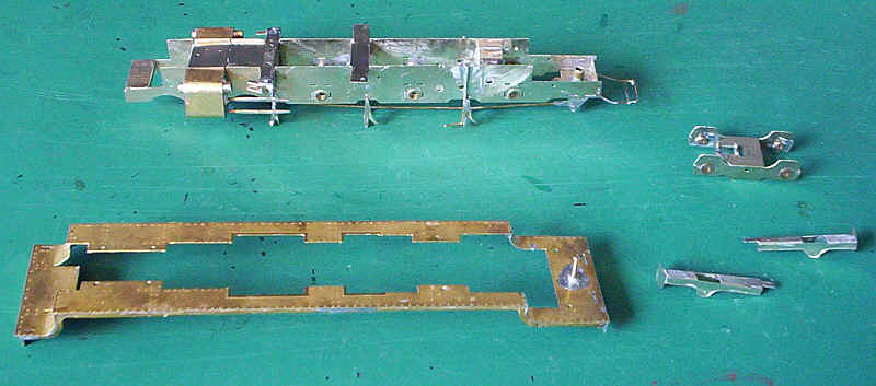
The photo below shows the main frames complete with brake gear and one set of sand pipes in place. The cylinder/ slide bar assembly is in place but not attached permanently - the front drivers have to go in first. The bogie is going to be a loose fit with no lateral spring as designed - I suspect there would be problems on my tight curves if I used this.
The two motion brackets have been folded up - there appears to be an error in etching here as the crease for the folds are on opposite sides of the nickel silver and when folded into a U shape the holes are not aligned. Surely all etched folds have the crease on the inside?
The cylinders have now had their slide bars attached and short lengths of brass tube soldered in place at the front and rear tops and a large plasticard disc was super-glued to the lower front of the cylinders.
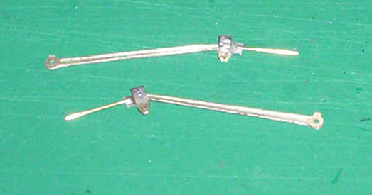
Whilst the kit includes all the brass and nickel silver etches needed there are certain parts, especially castings, that are missing. For instance, there are no crossheads. Having constructed the fabricated crossheads in the Worsley Works MR Compound kit I decided to do something similar for the Patriot. I cut three small pieces of nickel silver. All three had a hole drilled through sufficient large to allow a steel Lil pin to pass through.
Starting from the rear the procedure was as follows:
The pin had its round head file flat
This was then soldered to a rectangle of n/s 4 x 7mm and a hole drilled centrally. This passes behind the slide bars.
Another piece of n/s 4mm by 8mm had a hole drilled at one end and at the opposite end a length of .9mm brass rod (for the piston rod) was soldered on. This was passed over the pin but not soldered in place.
The kit's connecting rod parts were soldered together and then passed over the pin, again not soldering in place.
The front piece of the crosshead was made from a 4 x 10mm piece of n/s. Two holes were drilled, one for the pin to pass through and the other, near the bottom to connect to the valve gear. The lower corners were then snipped off to leave a hexagonal shape.
The pin was then soldered to this last piece and trimmed and filed smooth.
At this stage all parts were thoroughly cleaned and the cylinder assembly and frames spray painted.
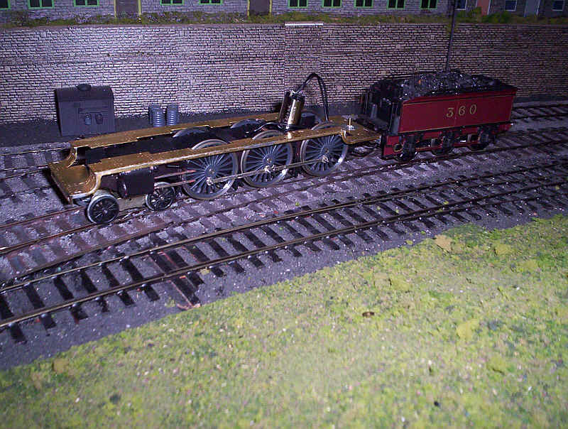
My initial thoughts about the method of propulsion were to use a spare Portescap motor/ gearbox and the photograph below shows this in place on the partially assembled chassis. I've wired the motor up to the self propelling tender from my MR 4-4-0 No 360. However, testing running suggested that I'd get good results using both the Portescap and a tender drive unit so, initially I decided to pursue this option.
However, on assembling the valve gear I ran into numerous problems, which I won't elaborate on, other than to say that plastic centred wheels, complex valve gear and my rather heavy handed constructional techniques don't get on. The result was that I abandoned the entire project and removed all the valve gear and wheels. No more "big LMS locos" seemed to be the result of all this work.
However, a few days contemplation saw me wondering whether building the loco as either a static model, or one with just a free rolling chassis and a powered tendered (as with all my MR locos), could be the answer.
So, I started to reassemble the chassis. Eventually, after several near disasters when sections of the valve gear refused to do what I wanted, I arrived at a free rolling chassis which is going to be propelled by a tender drive unit in the Fowler tender.
I'm still puzzled why I can't get the return crank to solder rigidly in place - presumably it's because the crankpins are not actually held firmly in the plastic wheels even when the "lock nut" is tightened. (Note added later; I ended up discovering that the problem was that the crankpin screws were, indeed, turning around as the cranks revolved. A dab with a soldering iron melted the screw head into the wheel and appears to have solved the problem)
I must admit that I wish there were Romford wheels available in S scale. I've assembled well over a dozen locomotives with Walschaerts valve gear with none of the problems I've had with this model!!
Surprisingly, the locomotive will traverse curves as sharp as 36" radius.
Having produced a chassis that rolled I decided to move on to the next stage - the construction of the Fowler tender. The basic structure is precisely the same as all my tender drive units so go to this page for details.
One modification I've made to the original drive unit is to improve the pickup arrangements. I now cut a strip of paxolin printed circuit board and screw it to the underside of the Airfix keeper plate using the two crosshead screws already there. The copper is gapped and nickel silver wires solder in place so that current pickup is off all six wheels. This method makes it unnecessary to have any pickups on the loco itself. The loco and tender are connected using a wire loop on the loco drawbar and a vertical bolt at the front of the tender - simple and almost foolproof.
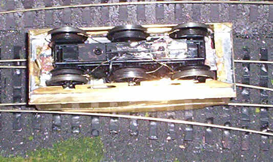
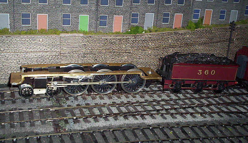
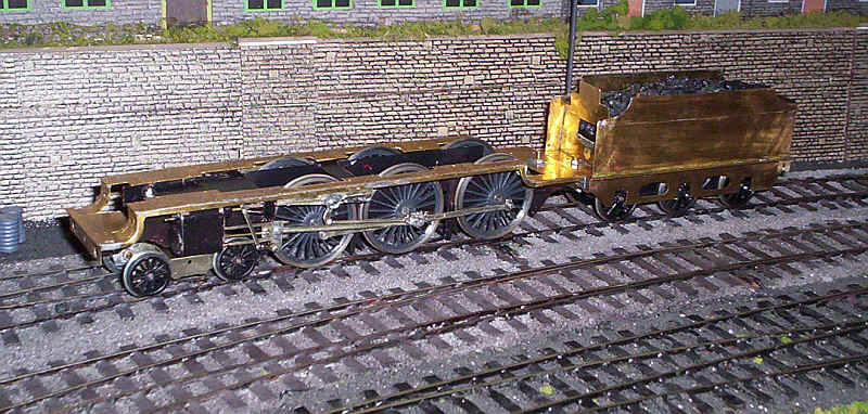
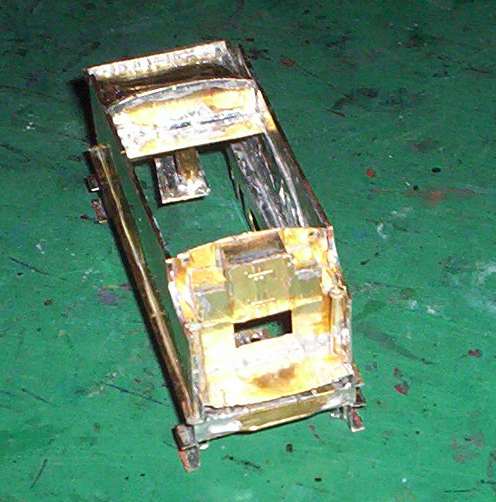
The chassis, running plate and tender carcass are seen below during test running.
After cutting a length of brass tube to the correct length for the boiler barrel and slipping another length over it for the smoke box, I decided a mock up from card for the fire box and boiler front would be useful before cutting any more metal.
The mock-up was certainly worth the effort because it showed me quite clearly that the boiler tube was definitely to small in diameter. How I dealt with that problem can be seen later on. The next part of construction was building the fire box. Fortunately, the Patriot had a nice simple one with flat sides and top with just to bends to worry about. Two ends were cut from brass sheet with cut outs for the driving wheels. I then measured the rectangle of brass for the sides and top of the smoke box wrapper and bent a right angle bend for the first of the top corners.
To do this I simply marked where the curve started, pressed a file along this line and lifted the loose end of the metal to form a nice round corner. The smoke box wrapper was test fitted and then the second curve was bent in the same way. Success first time. The wrapper was then soldered onto both firebox ends.
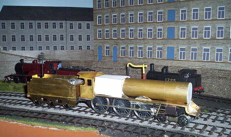
Test fitted to the chassis and cab it looks good!
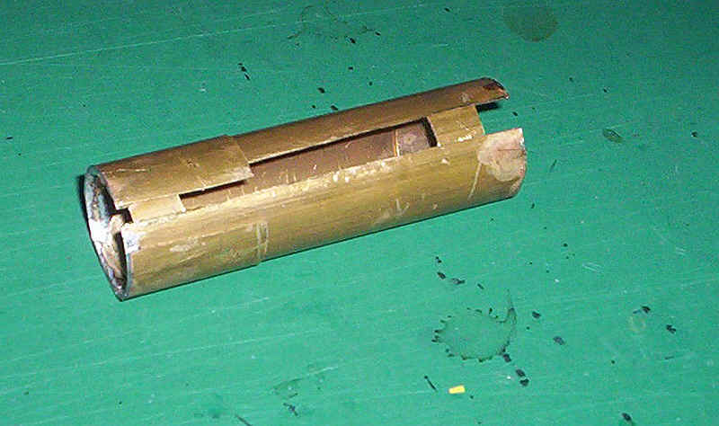
As mentioned above it was obvious that the diameter of the brass tube I'd been supplied with was too small. The solution was brutal but simple. The main boiler tube was split longitudinally and two short lengths of tube were slid inside as shown in the photo. It still wasn't quite big enough so I slipped four slivers of brass in between the short tubes and the main outer tube. As can be seen the smoke box wrapper wasn't in quite the right place when I took the photo. This had to be adjusted so that the openings at the bottom of the boiler and the smoke box coincided with each other. The boiler was the soldered together at the ends and at the interior spacing tubes.
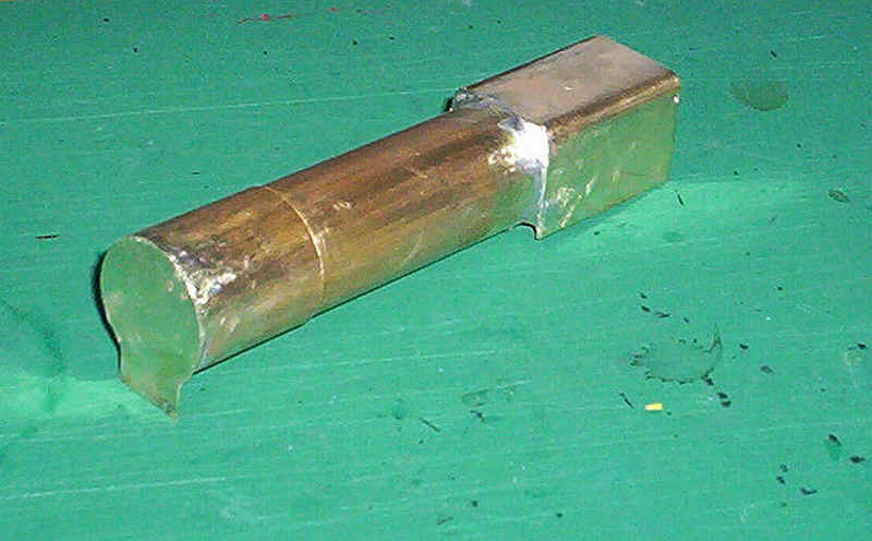
Moving on the boiler has been soldered to the firebox and a smoke box front and saddle added and filed to shape. Lots of heat was applied with my big soldering iron and then quite a lot of time spent filing solder away to give the correct profile.
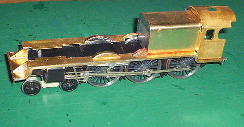
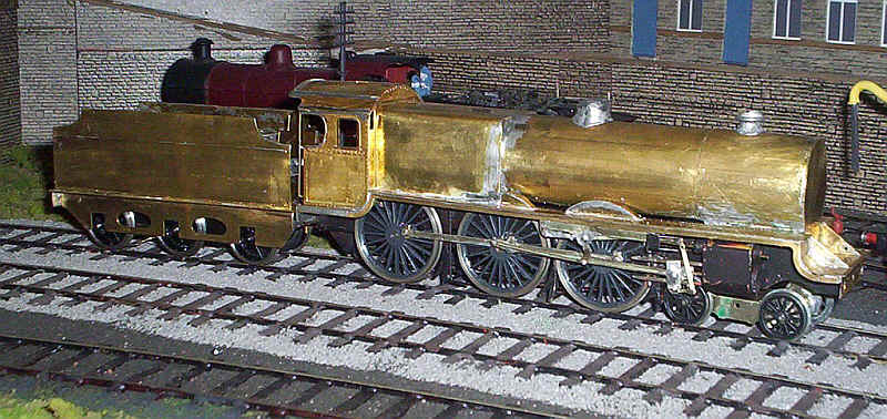
Moving on two the next stage at last it's beginning to look like a Patriot. The boiler and firebox are soldered in place and the splashers added. The cab is still loose but fits neatly.
On first impressions there might not seem to be a great deal of progress between these two photos, but there are many hours of (often painful!) work. The cab is now complete with beading, rain strips, handrails and footplate interior in place and the entire cab unit is now soldered and bolted firmly in place.
One of the aspects of this kit that has been worrying me is the absence of any suitable dome or chimney. However, delving through my parts box I came across some castings for a Midland 4F including a variety of domes and chimneys.
One of the smaller height domes was filed to shape using various drawings and photos as a guide. I'm not sure if it's quite right yet but it's pretty close. I think final shaping may wait until it's stuck firmly in place on the boiler.
The chimney required even more drastic action. I think it started life as a Stanier chimney for a 4F but again I'm not certain. I cut off the whole of the top directly underneath the lip with a micro saw and filed this absolutely flat. The base was then reduced in height by about 2mm by the same method and filed level and flat. The two parts were then joined together with super glue. To ensure they stay together I then drilled a hole through the new chimney and super-glued a length of 0.7mm brass rod in place with about half an inch stick out through the base of the chimney to locate it in the correct place on the smoke box.
The whole process of fabricating these two parts was somewhat painful and a few days "off model making" are called for!
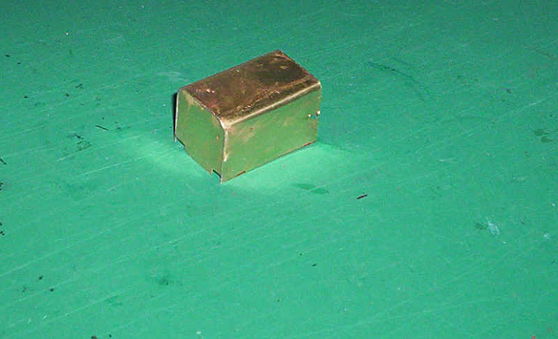
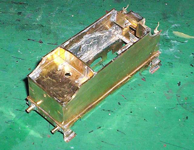
Attention now turned to completing the tender. As usual for these smaller MR based tenders I'd used a re-gauged Airfix Royal Scot unit. However, the Fowler tender needed a slightly different mounting method to usual as I wanted to use the rear half of the tender top as supplied in the kit. This because the rear coal partition is in front of the position of the rear securing screw. The method I used for overcoming this problem can be seen in the photos below.
In the right hand photo you can see a length of brass tubing, just big enough in diameter to allow the self tapping screw to drop down and through the hole in the plate that secures the tender body on to the drive unit. A hole was the drilled through the tender top directly above this tube allowing access for a smaller crosshead screw-driver.
The rest of the body was assembled as intended by the kit designer. All that will be needed to complete will be a drop-in section covered with coal and as much weight as possible.
Progress on the tender and loco itself includes coal rails on the tender and steps on the locomotive. All of these have been strengthened by adding lengths of wire; lengths of 0.45mm behind the coal rails and 0.9mm behind the steps on the locomotive. I couldn't resist propping the smoke deflectors in place to see if the model is going to look like a "Patriot".
I decided to turn my attention to completing the tender with its numerous detailing parts. There's nothing much to say except that I strengthened the coal rails with brass wire soldered on behind the horizontal bars as the original frets were hopelessly fragile. Various brass castings for the water filer, water dome, vents and handbrakes were added together with the white metal tender springs. As usual these don't quite line up with the wheels as the Airfix drive unit is slightly under-scale but once in operation I never notice the discrepancy.
Returning to the loco an afternoon was spent drilling out all the holes for the firebox plugs, handrails and ejector pipes; it's a slow and laborious task usually done when I have the house to myself!
Then I cut some brass tube for the steam pipes to the cylinders. They're almost, but not quite, hidden behind the smoke deflectors so had to be added. A length about 8mm long with the ends cut at an angle were then soldered to the running plate and the smoke box. Plenty of heat was needed to ensure a good joint.
The handrails were added using a mixture of long and short Alan Gibson handrail knobs. The long ejector pipe (at least that's what I think it is) was secured using split pins.
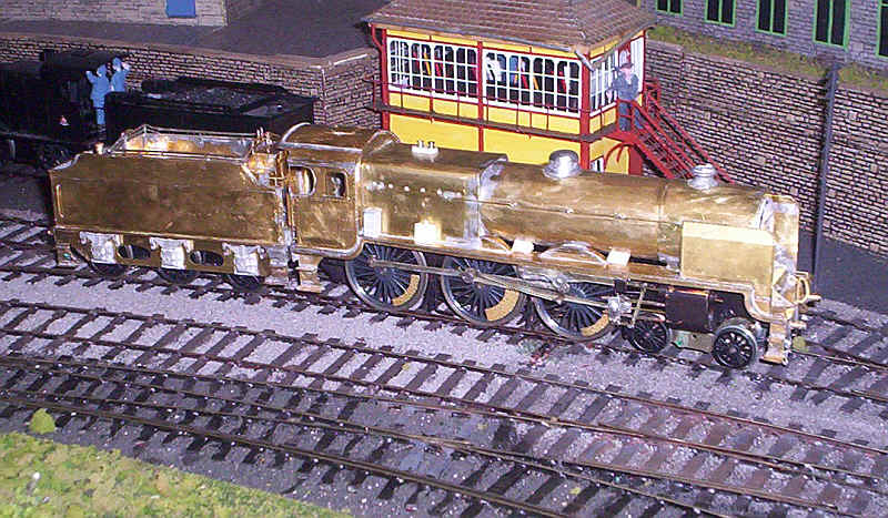
How to fit the smoke deflectors was a question that had been puzzling me for some time. The kit's instructions makes absolutely no reference to this problem. My solution was to solder to brass spacing strips on the back of the deflectors so that they would touch the boiler at its widest point. The deflectors themselves were bent to the correct profile and then soldered to the running plate, with the strips touching the smoke box and ensuring the deflectors themselves were vertical. The deflectors feel rigid and obviously can't move inwards because of the spacers. Whether I secure the strips to the smoke box I've not decided. If I do it will have to be with a little epoxy resin as there's no space to get a soldering iron to them.
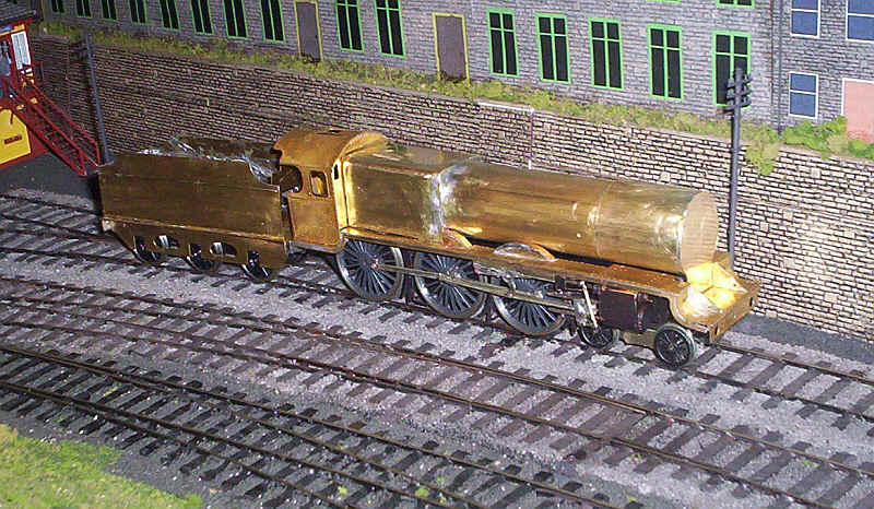
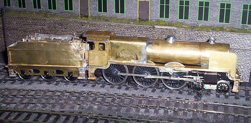
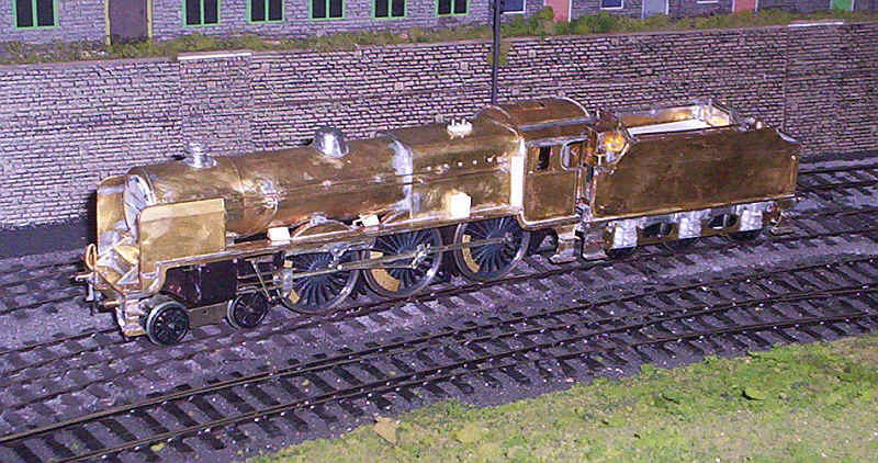
The photo below confirms that this model is obviously an un-rebuilt Patriot. I'm not quite happy with the height of the dome which might need a little more filing to get it right.
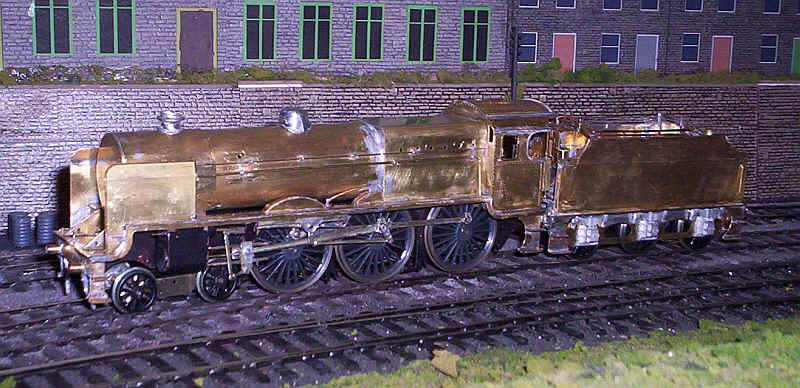
A few hours spent adding details brings the loco "alive". The raised area under the smoke box with the tailrod cover for the middle cylinder, sandbox fillers, nameplate mounting plate, injector pipes, AWS battery boxes, safety valves were all added from brass, wire and plastic. The smoke box door was made from plasticard discs and microstrip. finally the balance weights were glued in place. A very basic firebox back was put in the cab - the crew will obscure most of the cab interior anyway so why bother with unseen details? Time is short...
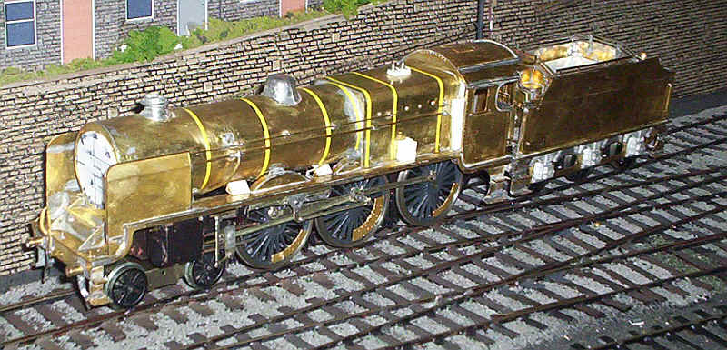
All that remains to do now is added the various boiler and firebox bands from PVC tape and the loco can be painted.
The final stage with the boiler bands applied using self adhesive PVC car lining tape. There'll be a final cleaning and then the loco will go into the paint shop to emerge hopefully in BR lined green.
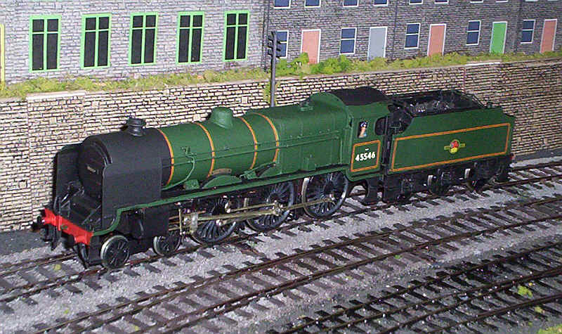
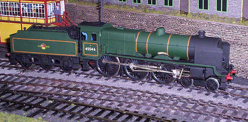
The two photos below show the model with its identity obvious; 45546 "Fleetwood". I saw this loco, aged seven, at Crewe in 1959. Five years later it was allocated to Preston shed so was clearly a North of England loco, should I ever build a larger layout for my BR (LMR) models.
Painting used Railmatch green, with waterslide transfers, these being great fun to apply. I've decided not to apply any lining to the footplate valences as I suspect I'd make a mess of it. The transfers were then sealed with Humbrol matt varnish spray.
Needless to say there are numerous faults with the model. The dome is not quite the right height - perhaps I'll sort this out at some stage but overall I'm reasonably pleased with my first "large" S Scale locomotive. It's certainly been a considerable challenge, not made any easier by the difficulty of attaching the return cranks to the centre driving wheel. I much prefer the strength of Romford 4mm scale wheels and crankpins to the flimsy Alan Gibson ones.