British Railways wagons
LMSR D1812 van
The first wagon that I've deicded to build largely from scratch is a former LMS 12T van which lasted in service well into the 1960s.
Using a diagram from LMS Wagons by R.J. Essery I scanned the page and resized it to S Scale and printed out several copies on card. The vertical lines for the timber planks were scored with a biro and a cast metal door glued in place on the sides. The strengthening strips and the runners for the sliding doors were adde4d from lengths of 10 by 40 thou microstrip.
I had some cast metal ends with the correct pattern of corrugated ends so used these together with a box made from 1mm thick mounting board to form the sub structure for the van body.
The printed sides were glued on to the sub structure overlapping the cast ends.
I also had a fret with etchings for the strapping of these wagons. These have been added to the corners using epoxy adhesive - not the easiest of tasks to do neatly!
The van has now gained a rolling chassis courtesy of an etched brass kit. Buffers, axle boxes springs and couplings have been added as well as crude representation of the vacuum brake pipe bent from 1mm diameter wire. The roof is card bent to shape and coated underneath with a layer of eposy resin to strengthen it. The model is now ready for painting.
BR 12 ton van
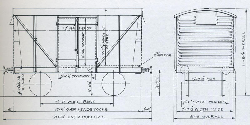
I've decided to build one of the vans with plywood sides - this is Diagram 1/213 - as then I won't have to deal with representing the planking on the sides.
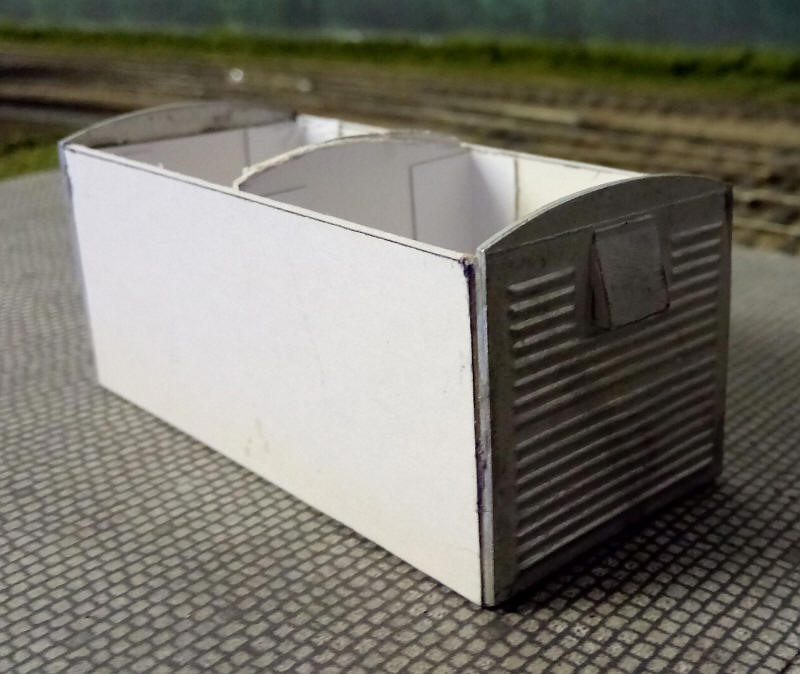
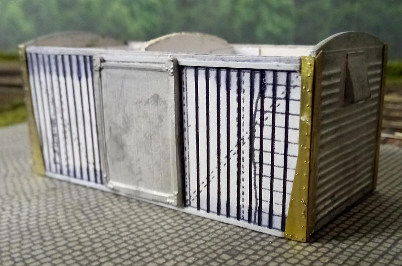
The next van to be constructed was one of the BR designed vehicles. I had two cast metal ends that incorporated the triangular side strengthening pieces. This makes construction a little difficult as the ends of the sides have to be cut at the correct angle to but up gainst the white metal.
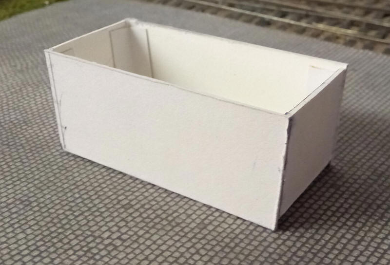
The method I used was to build an open box with sides, ends and floor as can be seen above. The ends slope in slightly...
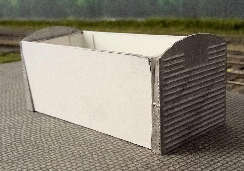
....so that when the cast ends are in place there is no gap between the metal and card.
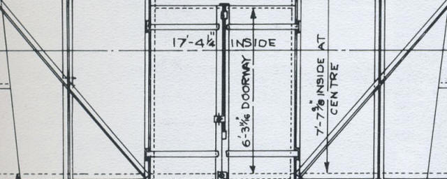
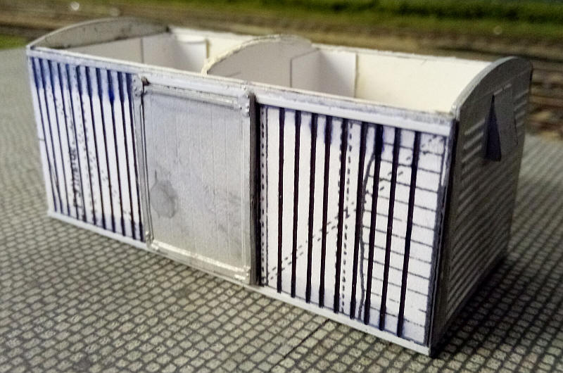
The diagram image was cropped and resized to the correct width and height and printed out on thin card.
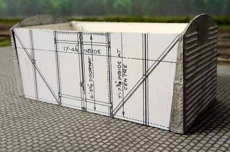
The printed card sides were then glued and trimmed to the correct angle before the ends were glued in place with Devcon. The card and white meatl ends match up perfectly with no gaps.
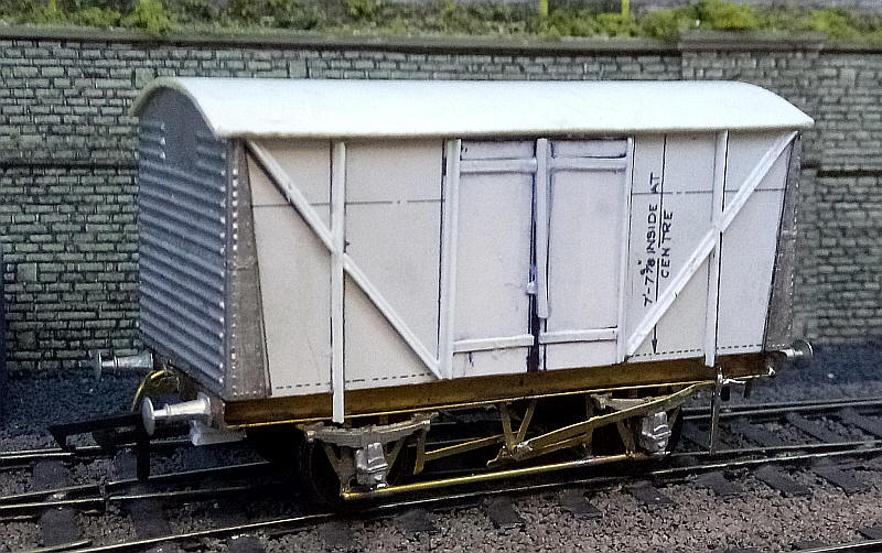
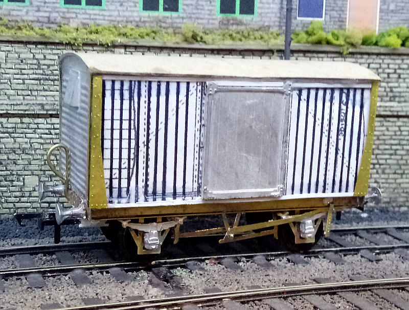
The finished model with etched brass chassis and plastic profile strips added. The tiebar between the W irons is simply a length of brass wire soldered in place and the cut to allow the pivoting axle to move.