Building a BR E44 electric loco
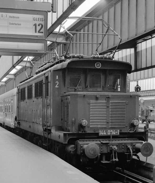
For this next project I am attempting to build a much more complex electric locomotive - the BR E44 Bo-Bo. The photo was taken at Stuttgart Hbf. in 1980.
Once again I'm going to use some of the parts from Albrecht Pirling's pdf kits which he has made available free on the Internet.
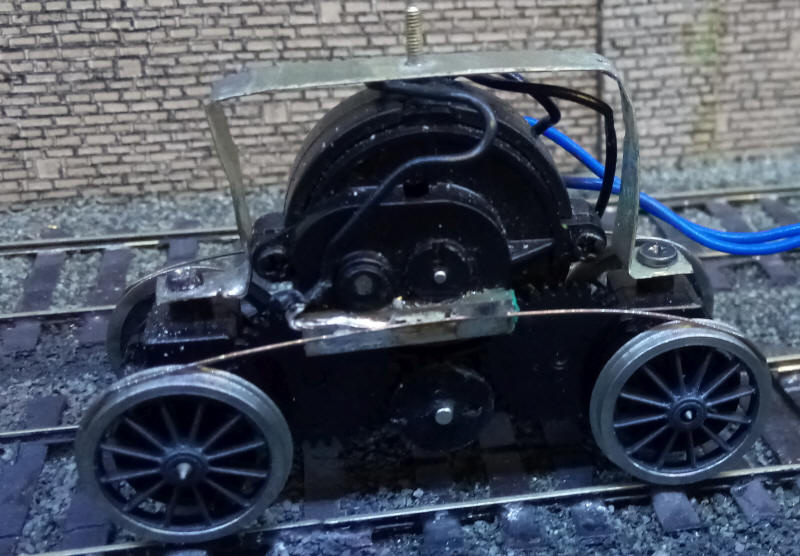
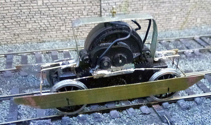
To power the model I am using two Airfix Royal Scot tender drive units which have exactly the correct wheel base for the E44. As usual I've replaced the OO gauge axles with S Scale ones, kept the original Airfix wheels and gears and added Alan Gibson S Scale spoked tender wheels. Simple metal strip brackets have been bent to a U shape and secured to the dive unit using self tapping screws in the original holes that secured the cast weight in the tender. A small BA bolt has been passed through a hole in the metal strip and soldered in place.
I did a mock up of the bar that will locate the bogie pivot points and also the sides of the loco's main footplate on which the original loco's body was constructed.
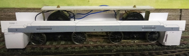
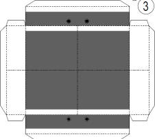
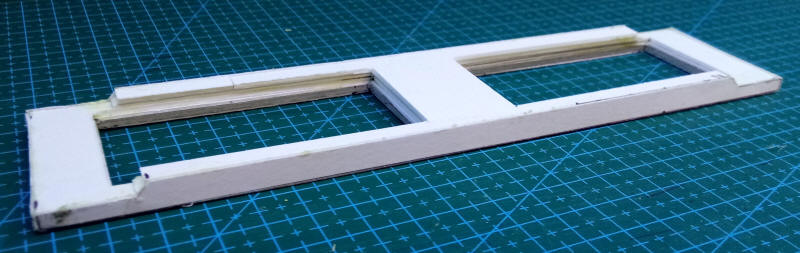
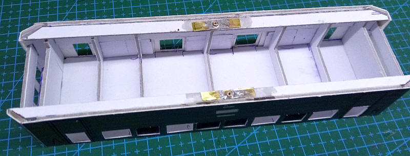
To make the basic chassis I fabricated this card structure which....
.....as can be seen will fit inside the locomotive's body.
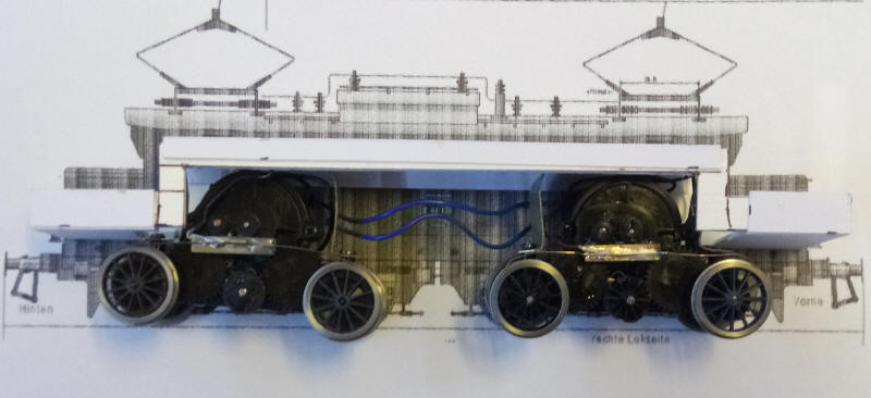
The bogie bolts are passed through holes in top of the frame which have washers superglued to both top and lower surfaces of the card. The motor bogies are connected electrically so there is 8 wheel pick up and running is extremely smooth.
The pdf kit has the sides of the footplate and the underframe for the non-working model drawn in three parts at 1:38 scale.

For my purposes I resized, cropped and rejoined them to S Scale amd then used this as a template for the part I needed for the main footplate.
The main footplate assembly shows the holes for the motor bogies and the lower sections at the end where the loco's bonnets sit..
The next task to be tackled was turning the tender drive units into ssomething that resembles a bogie. The pdf comes with parts that can give a realistic representation but they need to be secured to the mechanism securely. The method I have chosen is to have an internal bogie side frame out of sheet brass onto which the card parts will be attached. The brass is hung from pieces of wire that are soldered onto the metal strip that is used for the bogie pivot point.
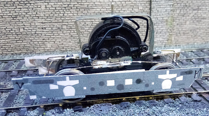
The bogie side frame has been glued to the brass - the M stands for Mitte (middle) and the V for Vorne (front) so I've marked these to avoid any confusion during construction. The inside of the bogie will be strengthened with additional layers of card and a thick coating of epoxy resin.
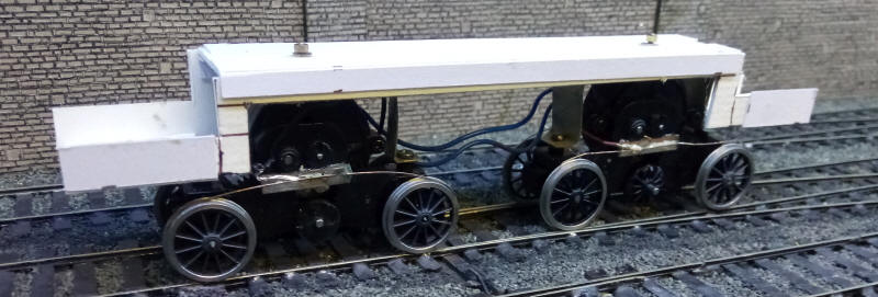
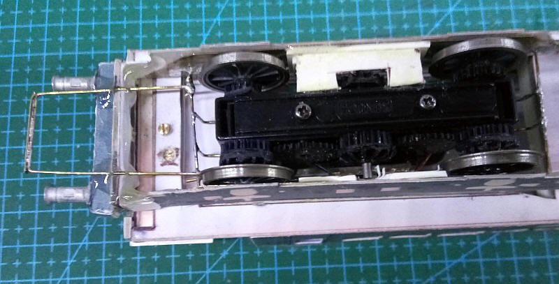
The footplate has now been secured with bolts to the internal structure, the motor bogies wired together and the E44 now has a working chassis ready for the addition of the loco's body. Most of the detailing work on the bogies will be left until the basic body has been constructed to avoid damaging relatively delicate parts.
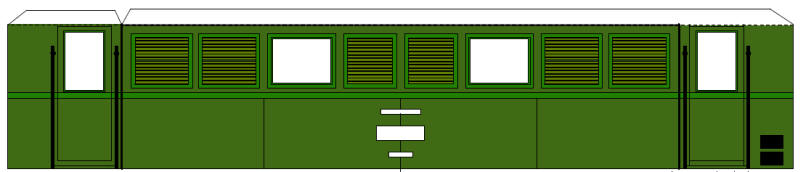
I'm now moving on to construct the loco body. This will need to be detachable from the chassis so cannot be assembled in the way it was designed for a card static model. The sides are handed with different numbers of grills on each side.
The first step was to cut out all the windows and teh space for the ventilation grills. On the real locos some have the grills recessed inside the body shell whilst others have them added to the outside. I chose the former. The grills are made from pieces of card scored heavily with a sharp biro ; these are then glued to the inside of the openings.
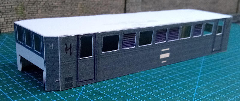
The cab ends have ahd slots cut in them to clear the chassis frame. The ends and sides were glued together and a piece of mounting card was cut to the exact size needed to hold the sides correctly and glued in place.
The body is placed loosely on the chassis.
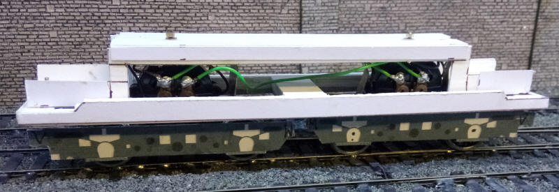
The body will be secured to the footplate part of the chassis by bolts passed through the footplate. Two bolts are in the centre of the main section of the body and are secured to nuts soldered to thin brass sheet. These are secured to the longitudinal strengthening strips that run along each side of the body.
The photograph also shows the various pieces of card that are inside the body to strengthen it and hold everything at right angles. There are certain compromises necessary to accomodate the mechanism, the principal one being that the cab space at each end has had to be severely restricted by placing a piece of card about 10mm back from the windscreen in order to hide the internal frame.

The bonnets at either end of the loco are made from a fold up assembly glue onto a base. I have had to modify these considerably to allow them to be joined to the main body and also to be fitted around the internal chassi structure. This involves multiple layers of mounting card within the bonnets.
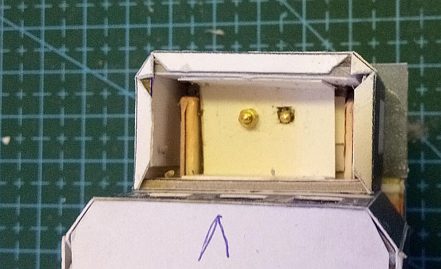
I've now added one of the bolts at the bonnet end. A piece of card is secured inside of the bonnet. The nut will be trapped in place with small pieces of card.
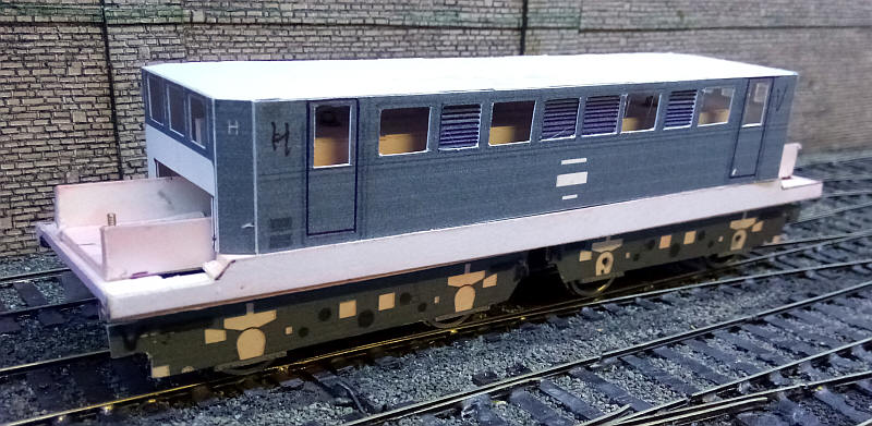
Both of the bonnets have now been completed and the body is now bolted to the chassis in four places.
The bufferbeams are made from a fold-up cuboid which I strengthened by gluing several layers of mounting card inside to make a solid block.
These were then glued to a piece of card secured to the outer ends of the bogies. The buffer beams stand out from the front of the footplate and on the real loco are mounted on the bogies. The buffers are 4mm scale BR heavy duty freight wagone buffers that are a reasoanble representation of those on the DB E44s.
To strengthen the bufferbeam assembly and also provide the coupling bar I've used a U shaped length of brass wire soldered to the cross wires within the chassis. The wire was passed through slots in the card fromt of the bogie and secured with epoxy resin to the underside of the bufferbeam.
The roof is a separate structure made out of shaped layers of mounting card cover with several overlays of thin paper and card shaped to the correct profile as can be...
...seen in this photo. The pantograph is one I've made for the BR E69 but gives an idea of what the model will look like. The basic structure of the loco is now complete with lots of detail parts to be added.
The model has progresses a little more with the two pantographs completed - soldered from nickel silver wire with card siscs for insulators. The pantographs are rigid and built to the same height as the BR E69 so that if I ever build a layout with overhead wires they can be set at a height just above the pantograph contsct strip.
Further details such as the axleboxes, springs, sandboxes, the raised central area on the roof and window light shields are all from card and from the parts in the pdf kit.
One of the problems modelling pantographs is the need to produce the numerous insulators. On my BR E69 I used card discs but this method didn't produce quite the effect I wanted. I repeated the method for the BR E44 (as can be seen in the previous image) but with numerous insulators needed on the BR E44 I wanted a better method. The solution was to coil some thin solder around a length of brass wire and then cut the coil into the lengths needed. The result can be seen above.
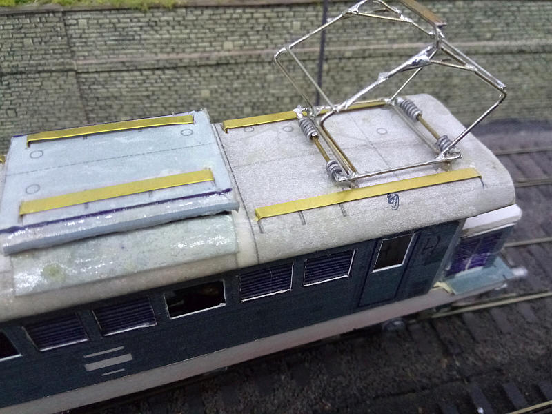
Also in place are the brass strips that will form the supports for the walkways on the roof. The strips are lengths cut from a strip of etchings. They are bent at the end s and then secured in slots cut in the card roof at each end.
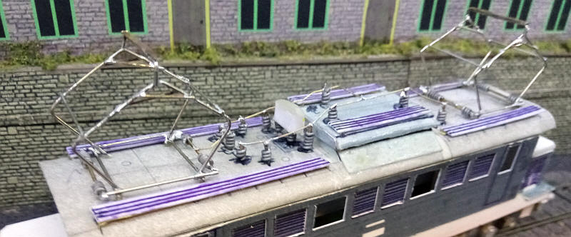
I've now added the complex layout of switch gear, insulators and wiring on the topof the roof. The insulators are coils of solder wrapped around short lengths of 1 mm diameter wire with fine brass wire connecting them . The timber walkways are represented by strips of card glued to the brass strip supports.
I've made some alterations to the pantographs - repositioning the lower legs to give a more realistic spacing at the bottom of the diamond shape and also adding the linkages between the legs. Whilst not perfect the pantogarphs are reasonably close in appearance to the real thing and importantly are strong and rigid.
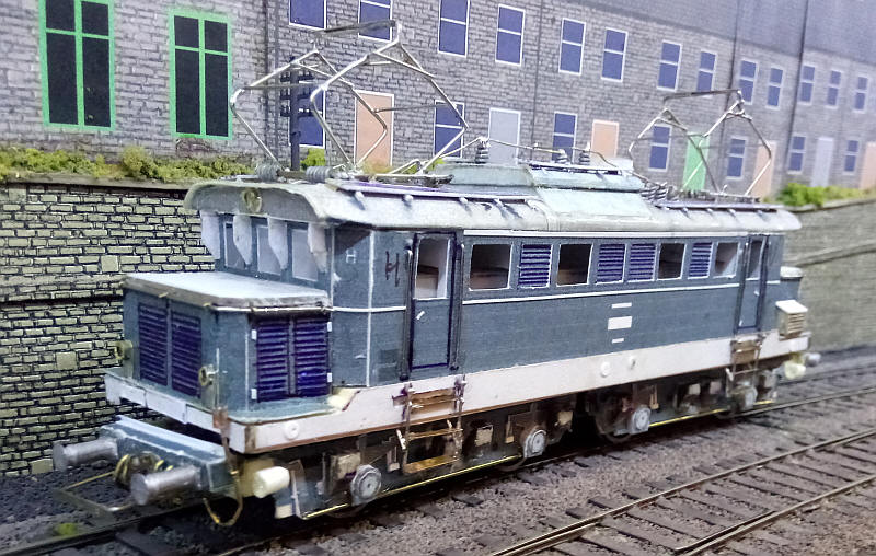
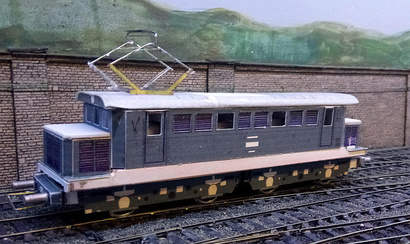
A large number of details have been added: handrails, cab steps, air brake hoses, electric train heating cables, beading along the body side and cantrail, hinges, brake pull rods, roof walk supports, headlights as well as the curious arrangement of cooling pipes on the side of one of the bonnets.
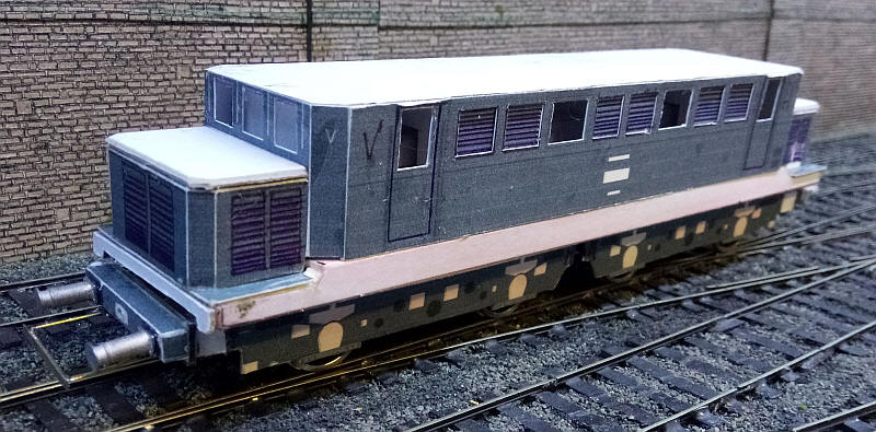
The model is now ready for painting.
 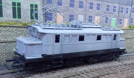 |
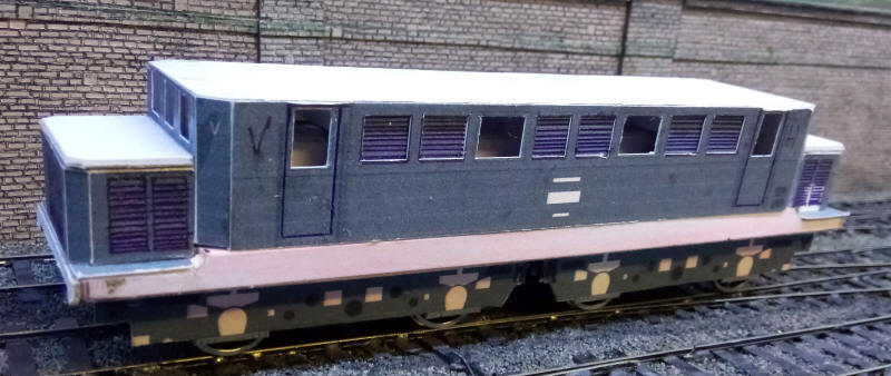
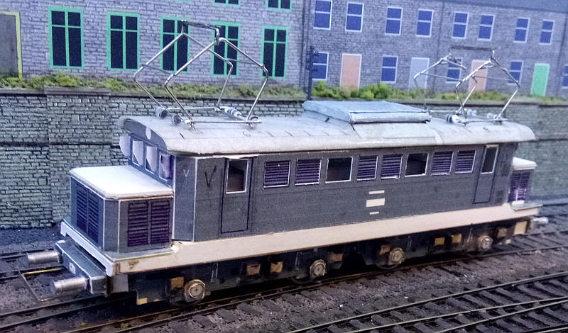
The model in grey primer.
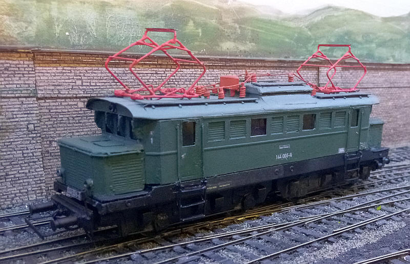
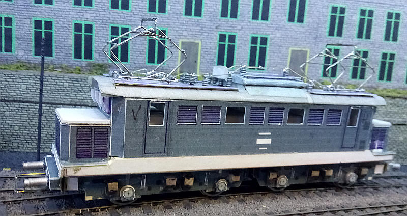
Viewed from cab 1 end. The lettering is from various transfer sheets by Modellbahn Decals
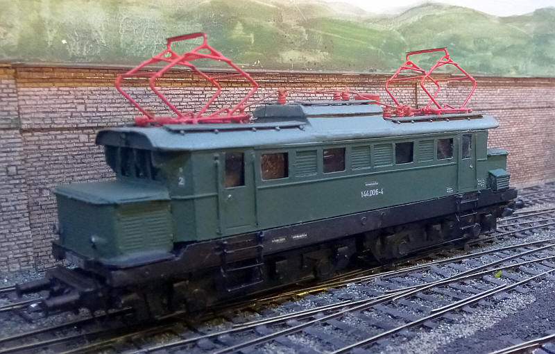
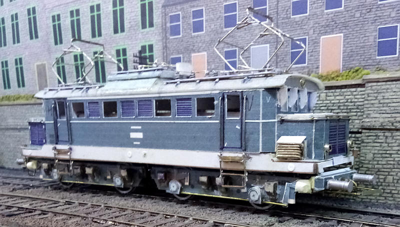
Viewed from cab 2 end.