Building an LMS Class 5
Any layout based on former LMSR lines needs a least one Stanier Class 5. Using the Alan Gibson kit as a basis this is my next project.
The kit is by no means complete with no boiler or smoke box but there is a cast firebox and I have most of the castings needed.
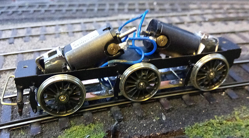
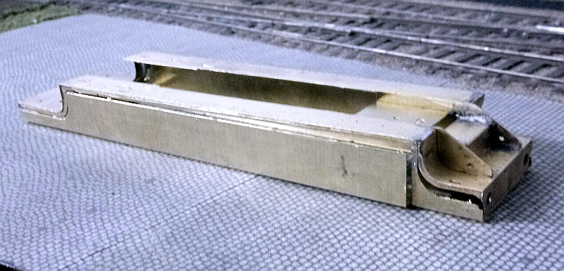
Construction started with the powered tender. This is a very simple one piece fold up etch. The wheels are Markits and the motors are from Mashima driving Markits gearboxes. The centre axle floats freely in vertically elongated bearings. A coupling bar is soldered to the rear axle guards at the correct height to match the Hornby couplings used on the rolling stock.
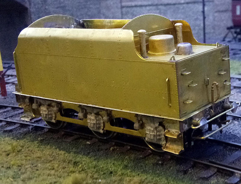
The basic structure of the tender is complete. Soldering the tender body with my low power small soldering iron was not easy as the amount of metal soon builds up into a heat sink.
The coupling arrangements can be seen with a bar across the buffers to prevent buffer locking and the coupling bar itself lower down. The tender has been weighted with about 110g of lead sheet to given sufficient adhesion to propel the unpowered loco and a train.
The easy part of construction is now finished
The locomotive
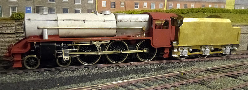
The construction of the Alan Gibson Class 5 starts with building the footplate. This is "eased" by initially being constructed around a fold up jig which incorporates the valances. Onto the top of this the various sections of the actual footplates are soldered. Once the flat centre sections and the two curved end sections have been soldered to the valances the jig is cut away to leave a rather flimsy structure.
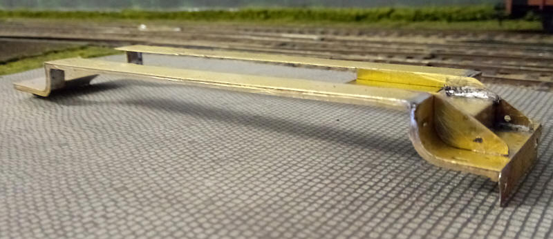
I've moved on a bit in this photo as the parts for the smoke box saddle, the front frame extensions, "piano" front parts and buffer beam are now in place.
I've placed the footplate unit back onto the jig to give an idea of what it looked like before it was cut away.
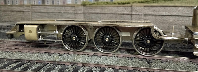
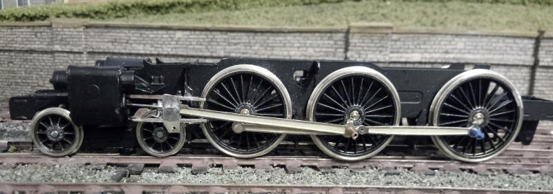
I've now moved on to the loco chassis. Initially producing a rolling chassis went surprisingly easily with the frames building up square using the tabbed spacers and the London Road bolt together alignment jigs. The instructions are as usual from Gibson kits basic to say the least.
There were problems with the slotting system for the cylinders and slide bar support brackets. The ones for the support brackets are simply not deep enough and if built in the way designed will result in the slide bars not being correctly aligned and also fouling the footplate. The slots in the frames had to be deepened to allow everything to sit roughly as needed. Also the angle between the cylinders and the slidebar supports didn't work well.
A lot of adjustments, including some brutal bending of the cylinder spacers to get the right angle, were necessary to get something approximating to what is required. Based on previous experience I decided to solder the cylinders and slide bar brackets solidly in place.
The bogie went together very easily. It's designed for the side frames to pivot but experience on other locomotives led me to solder it all together solidly. The bogie pivots on a bolt screwed into a nut soldered to a spacer between the cylinders. The wheels are Markits which are slightly undersized to allow trouble free running on my sharp curves. test running has confirmed that the model runs smoothly across the entire layout.
The kit of parts came without any crossheads so I've fabricated these out of nickel silver strip:
A backing plate, which slides behind the slide bars, has a 12 BA bolt soldered through a hole in it
A second piece, which fits in between the slidebars, has the piston rod soldered to it at one end. The bolt is then passed through a hole in metal.
The etched connecting rod from the kit is placed over the bolt - some oil keeps it from being soldered solid.
The front face of the crosshead has a hole in the centre and is held in place on the bolt with solder. Another small hole at the bottom of the metal is drilled to act as a pivot for the short union link.
After a lot of filing and fettling the crossheads and piston rods move freely.
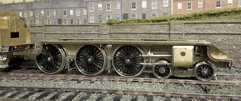
I've now assembled the coupling rods and permanently fastened the leading axle crankpins in place and filed to as thin an amount as possible to clear the back of the connecting rods. Even so the connecting rod has to be cranked a little to give clearance. The other rods are held in place temporarily with lengths of mains wire insulation. I've wrapped some lead sheet around the bogie axles to give some much needed weight. The chassis at this stage rolls smoothly so it is now on to the valve gear.
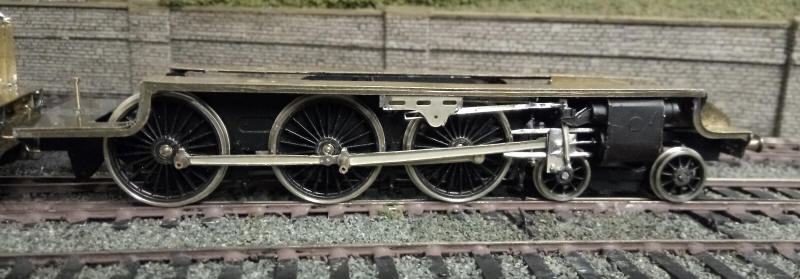
I've now added the anchor link, combination lever and the long radius rod. The radius rod is actually soldered in place to the brackets under the footplate as this makes assembly of this part of the valve gear somewhat simpler.
I had considerable trouble getting to this stage of construction. The method of attaching the slide bars to the cylinder is extremely flimsy - basically it is a very thin strip of nickel silver about 1/2mm in diameter and passes into the hole at the rear of the cylinder. Perhaps inevitably this snapped as I was reassembling the valve gear.
Fortunately, I have several Gibson kits that I 'don't intend to build so I used one from a LMS 3-cylinder 2-6-4T kit which has a much stronger locating point. Because of this problem I had to remove the radius rod and this also became distorted so I've replaced it with one from the 2-6-4T. It's a little shorter than it should be but I will put up with it! It is soldered firmly in place to give a secure pivot point for the combination link.
After fabricating the return crank, eccentric rod and the expansion link these were soldered in place. To locate the expansion link on its central hole I soldered a short length of nickel silver wire on a length of brass tube. This is located inside the bracket which supports the expansion and takes care of the alignment of the expansion link so that it doesn't hit the connecting rod as it moves to and fro.
The valve gear the loco is now complete and the chassis rolls smoothly. It's functional rather than accurate but once weathered the inaccuracies will be less obvious.
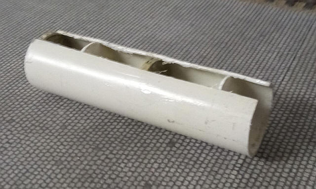
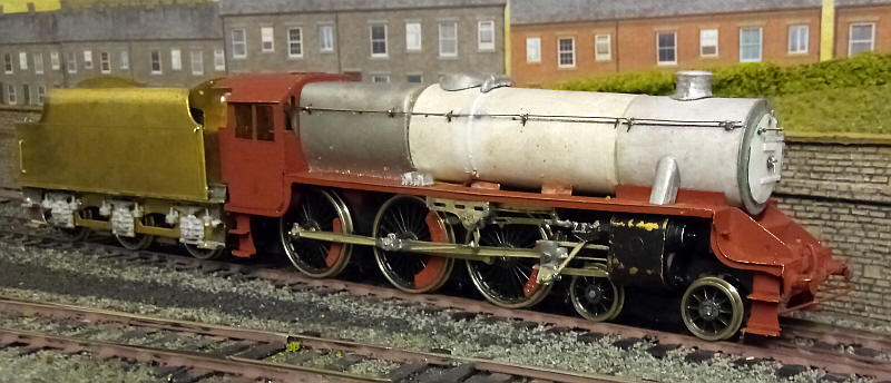
The next problem to be tackled is the boiler and smoke box. The plan is to use a length of plastic piping as the foundation for the entire boiler/ smoke box assembly and build up to the profile of the taper boiler using cardboard layers. A length of tube 90mm long was cut with the ends being squared off with a flat file. The tube was then split lengthways and two old one pound coins and some discs of 60 thou plastic card were inserted inside as can be seen. The coin on the left hand side of the photo will have the smoke box door attached, whilst the open end on the right slides over the circular protrusion on the firebox casting.
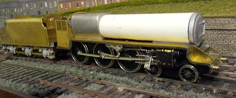
The firebox and boiler have been loosely placed in position together with the smoke box door. The next stage will be to build up the boiler cladding to the correct size.
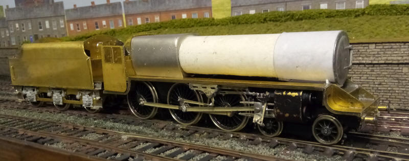
Things have moved on a little. The smokebox door has been glued to the one pound coin at the front of the boiler and the smokebox wrapper, made from a single layer of card secured to the boiler and up against the lip of the smokebox door. The card was then coated with two coats of petrifying fluid to harden it. The curved front of the smokebox saddle was cut from 60 thou plasticard and glued in place with epoxy - it can just be seen at the front end of the footplate.
After some thought I decided that the only way top proceed was to glue the boiler tube to the raised circular location point on the front of the firebox. Care was needed to ensure that everything was in line and at the correct angle, especially the smokebox door hinges need to be level. I will now be working on the tapered section of the boiler.
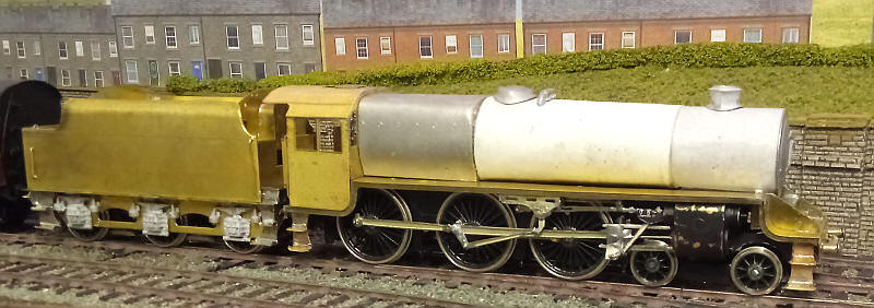
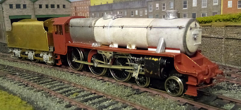
The taper boiler is now finished. To build it up to the correct size I added two 10mm wide strips at round the firebox end of the plastic boiler tube and another one in the middle of the boiler. I also filled in the gap at the bottom of the boiler with strips of card. Then a length of card about 70mm long was rolled and glued in place over these strips with epoxy and with the joint at the bottom - rubber bands held the card in place whilst it hardened.
The bottom of the boiler looked too high at this stage so I added another layer of card lengthwise along the bottom of the boiler and then add another outer layer for the tapered section.
Once set I drilled holes for the spigots of the cast metal chimney, top feed and dome.
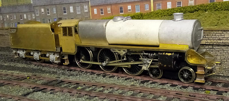
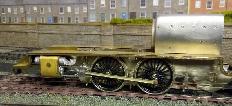
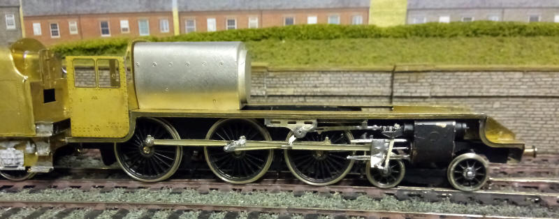
I've now added the cab doors and made a basic smokebox saddle from thin brass bent to shape. The boiler is held in position with a bolt through the cab front into the firebox casting whilst another bolt passes up through the smokebox saddle and self taps into the boiler.
As the model has a cardboard boiler construction has to be somewhat different to normal as the completed model cannot be given a really good wash before painting. I therefore gave the brass parts a thorough cleaning as normal and then sprayed the cab and footplate assembly in red-brown undercoat from a spray can. The boiler/ firebox/ smokebox assembly was then secured to the metal parts using a bolt at the firebox end and under the smokebox. The rear and bottom of the firebox and the underside of the smokebox were also covered in a liberal coating of epoxy resin to secure everything permanently in place.
As can be seen above the handrails and various other items of pipework and the steam pipes to the cylinders have also been fixed in place. The right hand side of the locomotive will follow.
I've modified the smokebox door to make the domed door more prominent. This meant filing off the door hinges and then cutting a disc of thin card which was glued to the metal. It was given a coating of superglue to harden it and then the hinges were added from microstrip. The smokebox dart was soldered up from a small washer and lengths of brass wire. The right hand side handrails and cast lubricators have been added as well as a strip of microstrip around the boiler to represent the cover of the pipe to the top feed. The brass balance weight from the kit have been sprayed and added to the wheels with epoxy.
I have been unsure how to add the two sandbox filers which are sandwiched between the footplate and the boiler; the solution was to cut to small pieces of brass about 10mm square and fold them into an L shape. These are soldered to the underside of the footplate and will give a firm location for the filers which will be made out of plastic and micro rod.
I still wasn't completely happy with the smokebox door for various reasons so this is the final attempt. I've also added the sandbox fillers - these were made out of a 3mm by 10mm strip of 60 thou plastic with a length of brass wire melted into the plastic. A length of biro tube was cut to the correct length and secured over the wire with epoxy. These assemblies were then secured to the brass location strips. The loco body is now ready for priming.
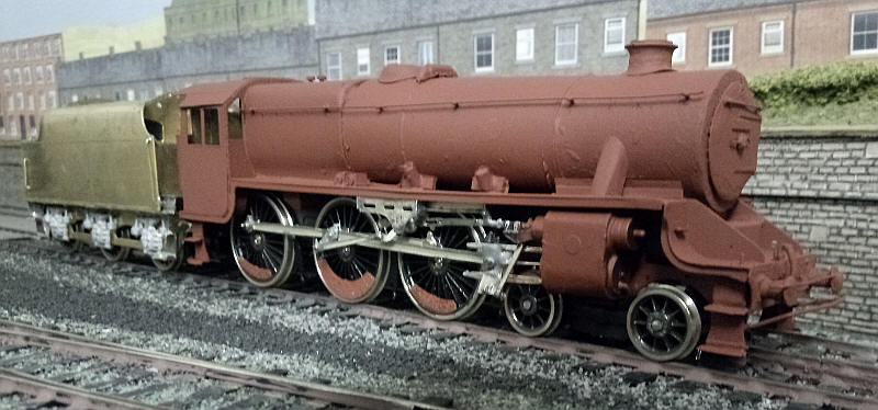
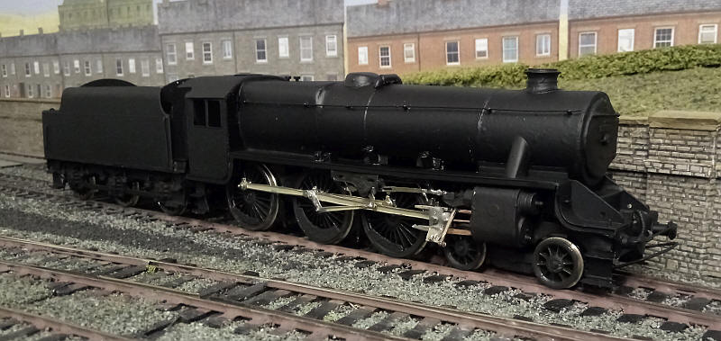
The moment of truth! A coat of primer reveals a few places where a little filling is needed - such as the underside of the smokebox door where there is a gap and one or two places where the surface of the card boiler needs attention. Nevertheless, it looks like a Class 5.
A very 'Black' 5
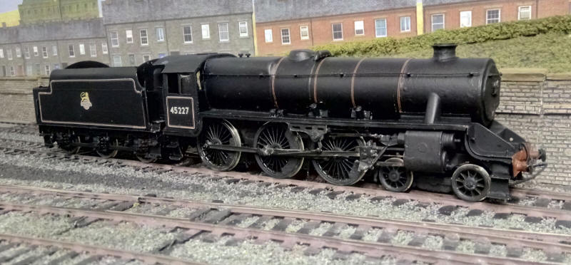
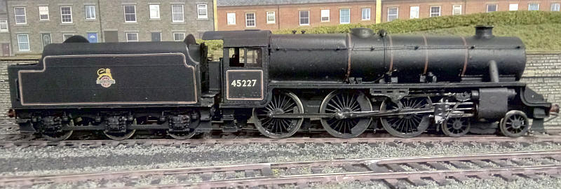
Two views of the fully lined out loco. Closer examination of the nearly completed model revealed that there was a fault in the position of the chassis in relation to the footplate - the cylinders were about 3mm too far back from the curved front of the footplate. It appears that there were inaccuracies in the slots in the frames for the cylinder assembly - this happened with both the Crab and Patriot that I've already built.
Slicing off 3mm from the front of the chassis solved the problem and repositioning it further forward has improved matters .
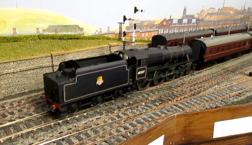
Loco No. 45227 spent all its life allocated to sheds in north west England. In 1966 I travelled behind it twice between Keighley and Skipton when it was allocated to Carnforth shed. I've chosen to model it in the late 1950s when it was allocated to Accrington shed. Therefore it carries a 24A shed plate (a Modelmasters transfer).
The model happily copes with the 36" radius curves and has more than sufficient power to haul a t least a six coach train, although the maximum on Pendle will be three coaches.
I shall leave the loco in ex works condition until I summon up the urge to weather the model.
To see the Class 5 in action click on the photo below. Depending on your computer or device the film may start straight away, need clicking on to start or the file itself will be downloaded before you can play it.