Deutsche Bundesbahn freight wagons
Obviously, as well as locos and passenger carriages I'll need a selection of freight wagons. A typical German branch line in the 1970s and 1980s would still have at least a daily service made up of vans, medium height open wagons, flat wagons with side stakes, oil tankers and self discharge open wagons. The initial plan is to initially build a selection of these using card as much as possible. Running gear will use fold up etched brass w-irons and 14mm Jackson disc wheels on S Scale axles.
Several of these types of wagon can be built using the free pdf wagon kits by Albrecht Pirling. I intend to use these as a basis but to modify the kits where necessary to produce wagons more suitable for use on an operational layout
Self discharge wagon
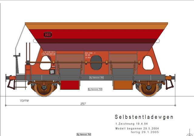
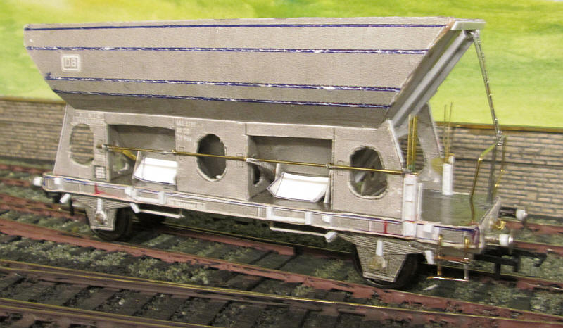
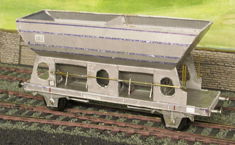
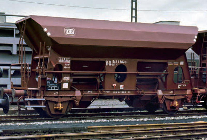
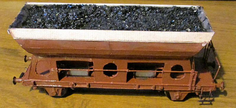
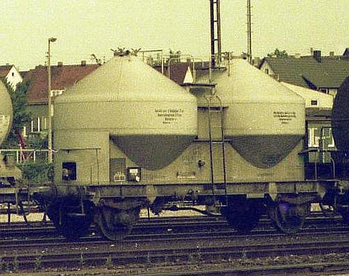
Thousands of these wagons were owned by DB - this one was photographed in 1980 and is probably one of the more complex wagons needed.
 |
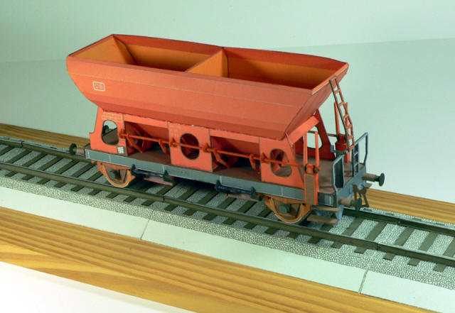 |
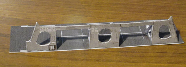
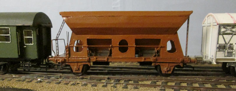
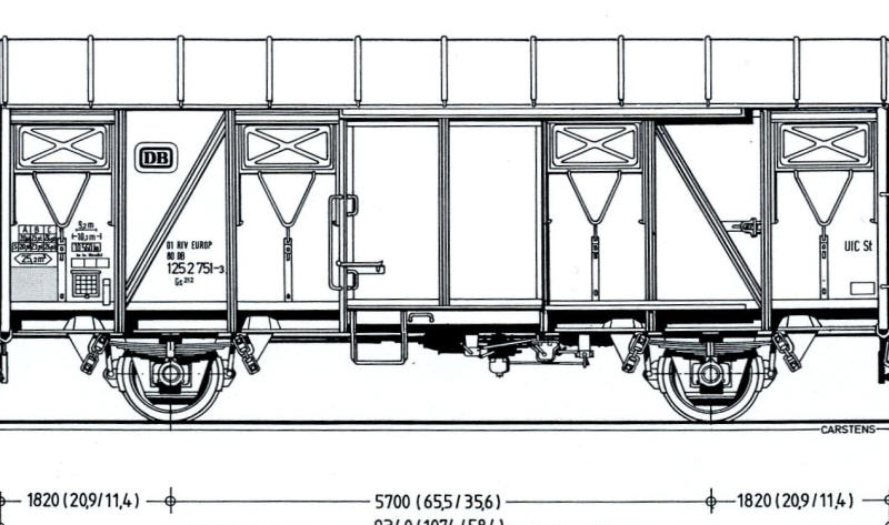
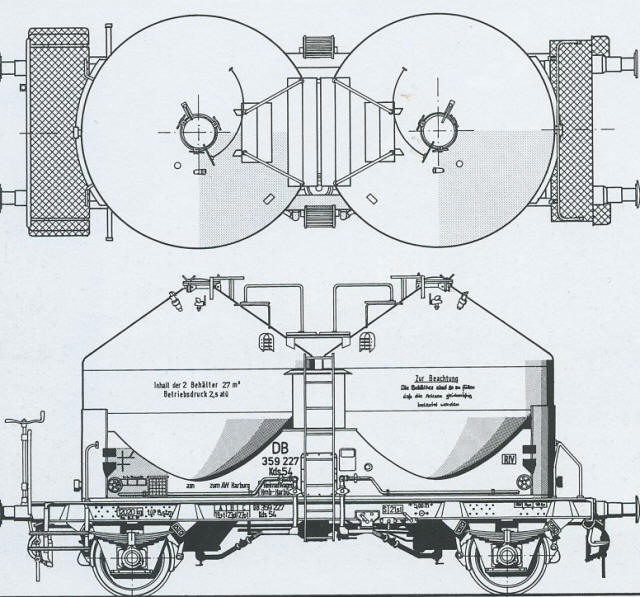
The images above show the side elevation and a completed model (in 1:38 scale) as built from the pdf self-coloured kit. There are several compromises made by the designer of the pdf such as a slight difference in the shape of the hopper ends but I'm going to accept these errors. What is necessary is to increase the strength of certain parts which will need repeated handling.
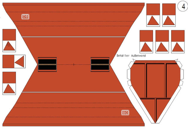
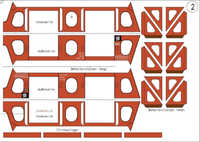
Above is one of the pages of the pdf with the main parts for the complex hopper. There is an inner and outer shell which after resizing to 1:64 folds up absolutely accurately and produces the main part of the wagon as seen below.
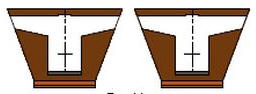
Virtually no adjustments were needed to produce this strong and neat hopper. The centre strengthening cross member and diagonally sloping interior is obvious.
 |
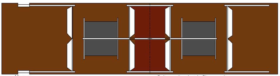 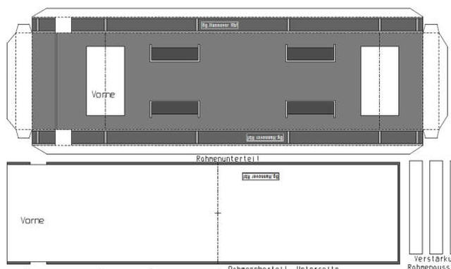 |
The next stage is to construct the wagon's underframe and the hopper support structure using the parts seen above.
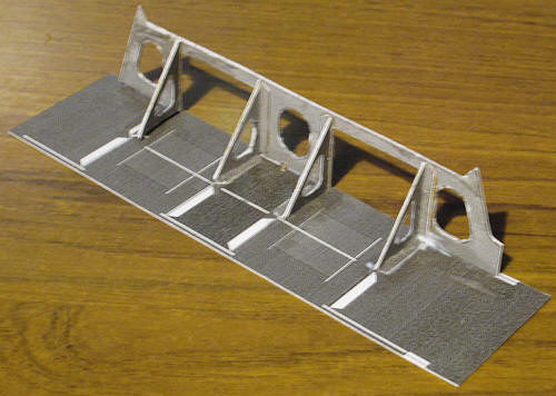
The hopper supports are complex and involve a lot of careful cutting out of curved relieving holes. The triangular pieces given considerable strength to this part of construction and will support the bottom of the hopper.
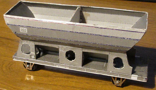
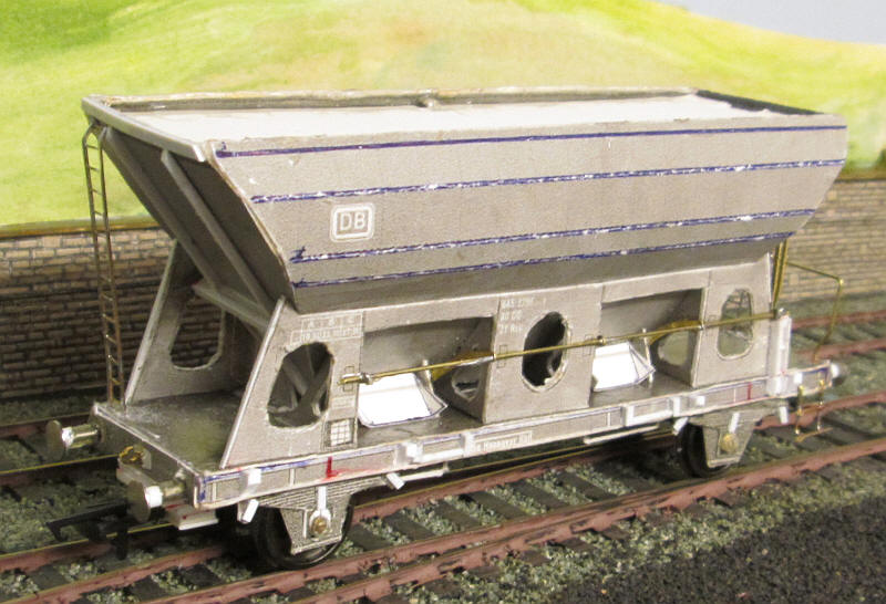
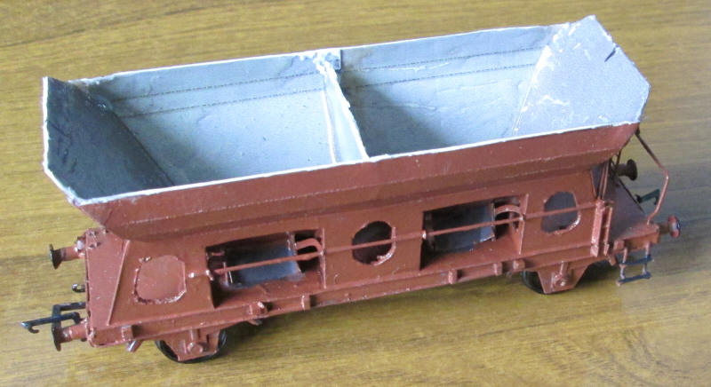
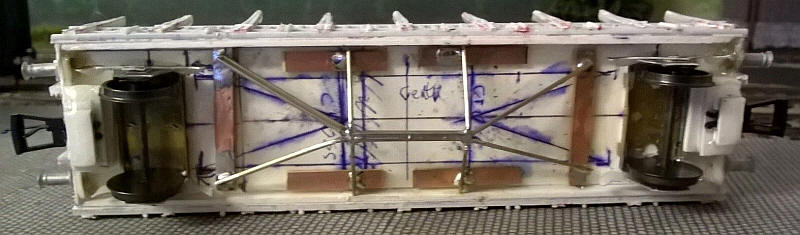
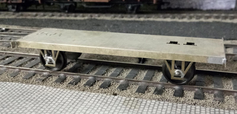
The hopper is seen in place on the wagon underframe with....
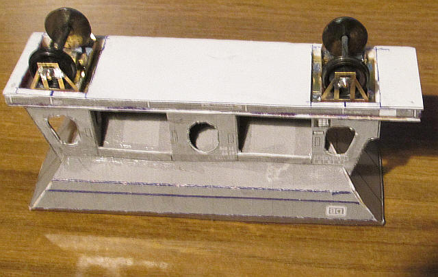
...this view showing how the wagon's underframe is made up of several layers of thick card with recesses for the etched w-irons.
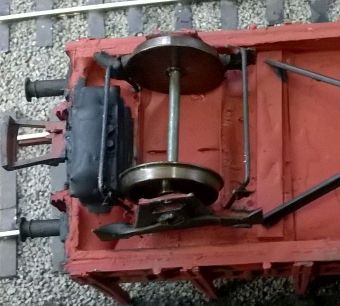
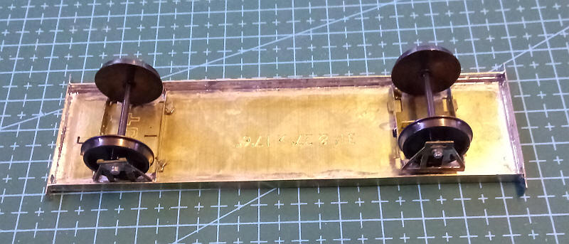
The photo above shows some of the detailing such as the discharge mechanism which is made up of brass rod and spare etched brass parts from British S Scale kits adapted to fit.
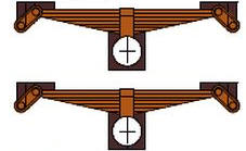
Even the springs and bearing mounting plates were made from card. These were cut out and secured onto the brass w-irons with two-part epoxy. The rear of the springs were then coated with another layer of epoxy to make them strong enough to cope with handling. Finally a 1mm section of biro pen tube was cut and secured to the brass bearings to represent the roller bearing axle boxes.
Construction is now complete. There have been lots of details added:
Couplings are the usual Hornby NEM type with metal hooks so the stock can be uncoupled using a magnet on a stick. Various strengthening bars made from square section microstrip plastic have been added to the ends. The supports for the discharge levers have been made from various small strips of microstrip. I've also added some additional parts to the discharge system underneath the hopper - these are just an approximation of some very complex and difficult to model parts. Ladders have been added at both ends as well as the shunter's platform handrail and steps.
Finally the inside of the hopper was coated with a layer of epoxy resin to strengthen it and a piece of thick card glued in place to provide support of the load of coal. Prototype photos show that this type of wagon was often loaded to the top of the sides and heaped in the middle so that is what I'll do.
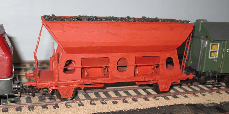
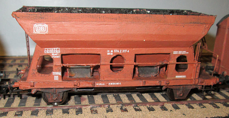
The wagon has now received its undercoat. DB wagons at the time I'm modelling were painted an all over a reddish brown colour including the underframe. Obviously the wagon needs painting in a darker shade as well as lettering - transfer sheets are available as for the loco and carriages but are yet to be ordered.
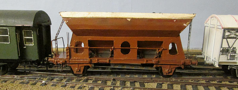
Oh dear! the model is too high.
I've always had some doubt about the accuracy of this model, particularly it's height. I've finally managed to obtain a scale diagram which confirms this. The model's hopper sides also don't slope in correctly at the top.
So I decided that some brutal surgery would be necessary. Basically this involved removing the entire top section where the hopper sides bend over and reducing the width of the second section of the side by 2mm. The ends also need modifying as the diagrams clearly show that sides bend in far more than on the original model. The photo above shows the top part of the wagon removed and the second section reduced in width and secured to the modified ends.
The new upper part of the hopper is now in place. This was quite a difficult job to do neatly and involved firstly attaching a long folded tab along the inner side of the hopper on to which was glued a 6mm wide piece of 1mm mounting card. This was then trimmed and glued to complete the inward leaning upper part of the hopper. Various other parts on the ends needed replacing before the coal load was trimmed to fit.
I wasn't happy with the gaps between the new and old parts so these were filled with epoxy and then first filed smooth and then rubbed over with a glass fibre pen to give a reasonably neat joint as below.
The final stage was to apply the decals which once again have been produced for me in S Scale by Andreas Nothaft at modellbahndecals.de.
Gs212 van
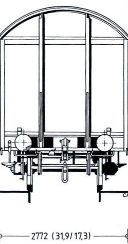
The next wagon I decided to build was one of the standard DB 4 wheel vans built in the 1950s and 1960s.
I photocopied and rescaled to s Scale a diagram from a German book by called "Guterwagen: Band 1 Gedeckte Wagen" by Stefan Carstens and Rudolf Ossig.
These were the printed out on thin card and glued to 1mm thick mounting card to give the basic sides and ends as below
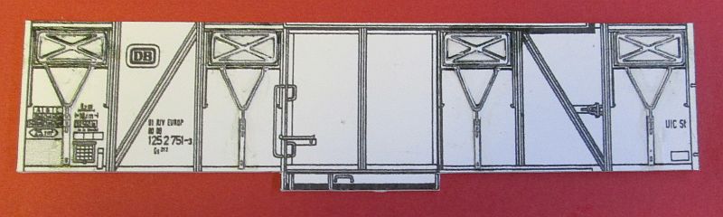
Another copy of the sides was made and the ventilator panels and the V shaped operating mechanism was cut out very carefully to produce the very flimsy shapes below. This needs to be done under a good light and with my optivisor magnifier.
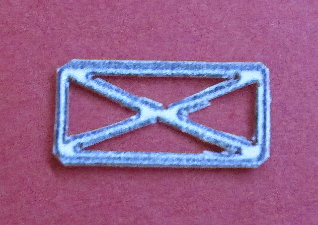
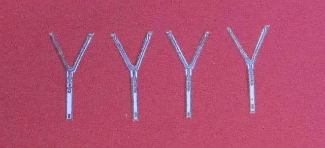
These were then glued in place onto the van sides in the correct place with PVA glue.
I've jumped on several stages here, as white card doesn't photograph well so I haven't illustrated every stage of construction.
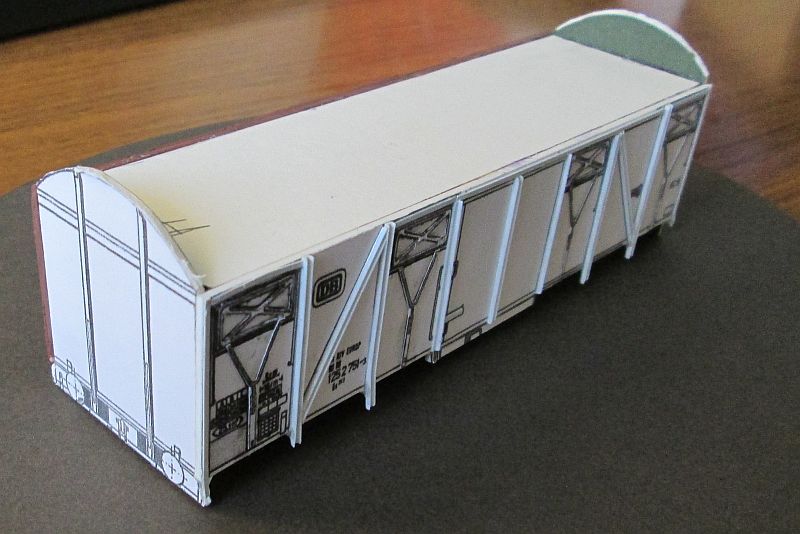
The pairs of sides have been glued to a base and a ceiling cut from 1mm card. The interior joints were reinforced with folded L shaped card strips to keep the sides vertical. The ends were cut out in the same way as the sides and trimmed to be a tight fit within the sides. Plastruct U and L shaped plastic channels and microstrip have been glued to the card sides by flooding the joint with polystyrene cement. One of the vertical channels was slightly bent in the photo but has now been straightened. Look carefully at the photo and you can see the tracery of card for the ventilator panels.
The model now has a roof made from two layers of card. A piece of thick card was glued vertically along the centre line of the van so that its top edge is exactly in line with the curved ends and supports the roof. The inner layer of the roof is glued to the ceiling of the van body with folded over tabs and uses the curved ends to form the precise curve need. Once this is secure the outer layer of the roof is cut exactly to size with the correct overhand. The roof ribs are 0.10" x 0.30" plastic microstrip fixed in place with solvent.
The numerous strengthening pieces along the base of the van were also cut from microstrip to fit in between the vertical U shaped channels. On the ends T section plastic profiles and strips of microstrip were also applied.
The buffers are 4mm scale BR 2'0" heavy duty buffers by MJT. These are very close to those used by DB.
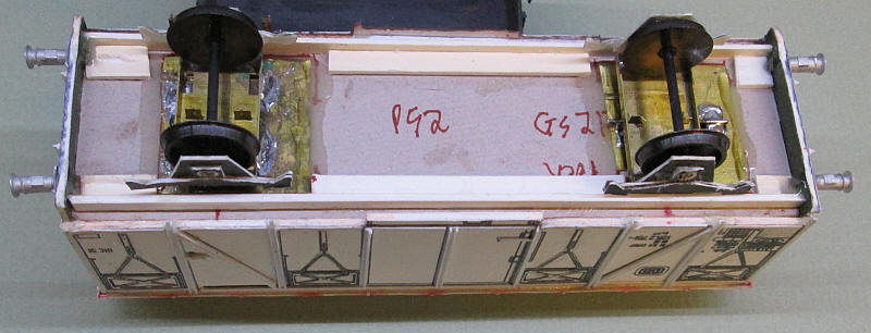
The view under the van shows the strips of thick mounting board card used to form the wagon's solebars and the method of mounting the rocking W irons to the underside of the card floor. Gluing the brass baseplates to the card with epoxy gives (fortunately) the exact height required. The springs and W iron plates are those from the self discharge wagon pdfs. They lack detail but when painted should look acceptable.
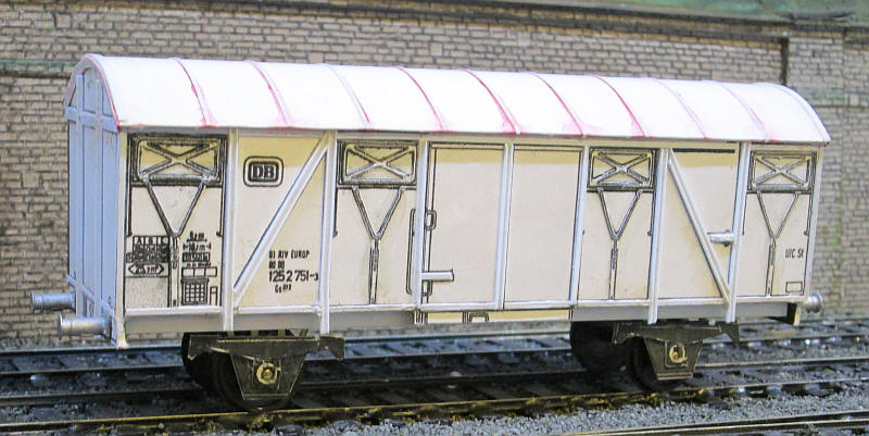
The completed Gls 212 van with ribs on the roof.
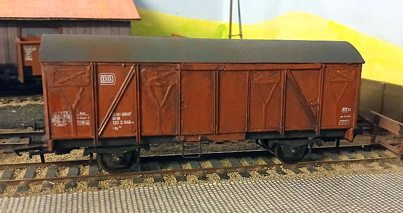
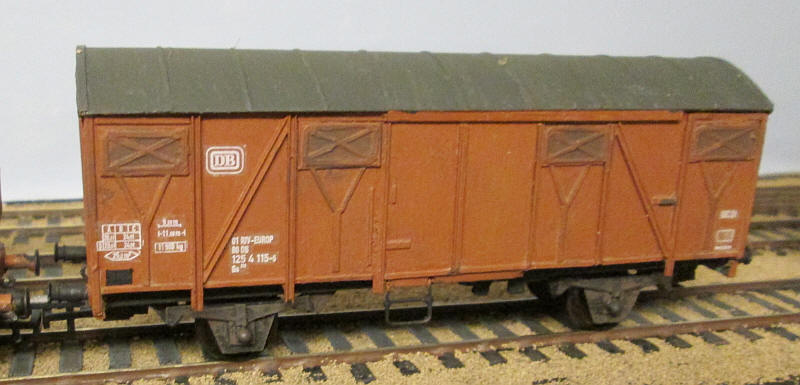
There were several varieties of the DB vans. This is a Gls 21 with a plain roof and four ventilators on each side.
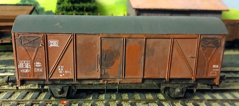
Gls 205 van with just two ventilators on each side and a plain roof.
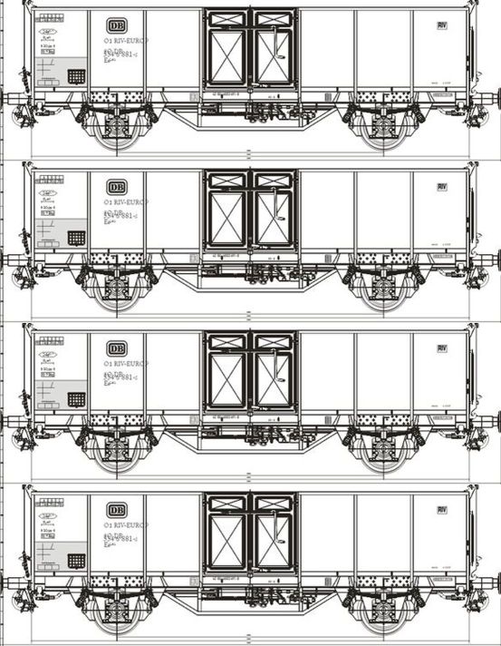
DB E040 (the former Omm55) 2 axle open wagons
Once one of the most common wagons in German freight trains tens of thousands of similar wagons were either rebuilt from pre-war vehicles or constructed from new so I clearly need several on the layout.
Obviously, the first step is to find a good drawing and here this website came in useful:
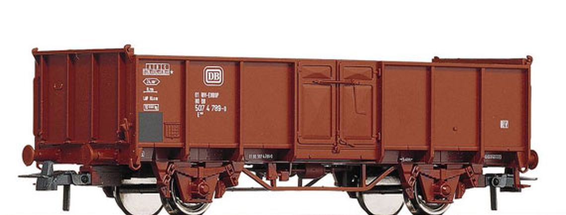
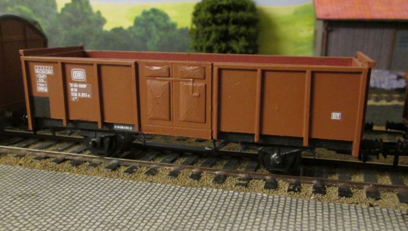
This is what I'm aiming for. Plenty of challenges to come I suspect, especially those doors.
http://www.m-niggemann.com/modellbau_lok_Gueterwagen_8plan.htm
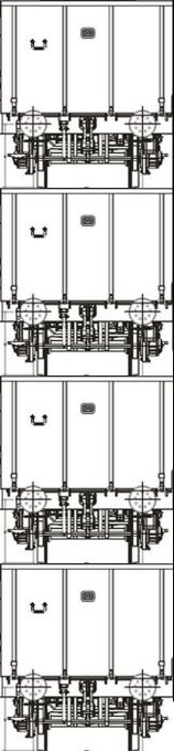
The diagrams were resized to S Scale and printed out in multiple copies as below.
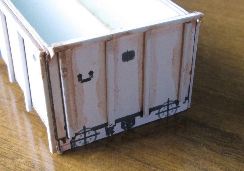
The sides and ends were printed out on card and trimmed to size. When cut out the sides I allowed sufficient card at each end that could be folded and the flaps folded to allow the ends to be glued in place as in the photos below.
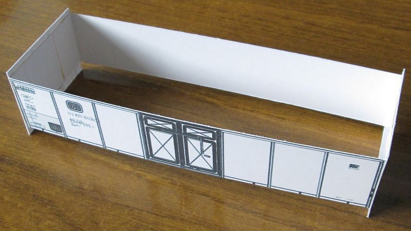
The next step is to strengthen the sides and ends by gluing thick 1mm thick mounting card on the interior of the wagon body and then add a floor of the same material. All joints were coated with a thick layer of Bostik adhesive and left to harden. Note that the ends are higher than the sides as both ends of the wagons have opening doors. The buffer beam is also part of the end.
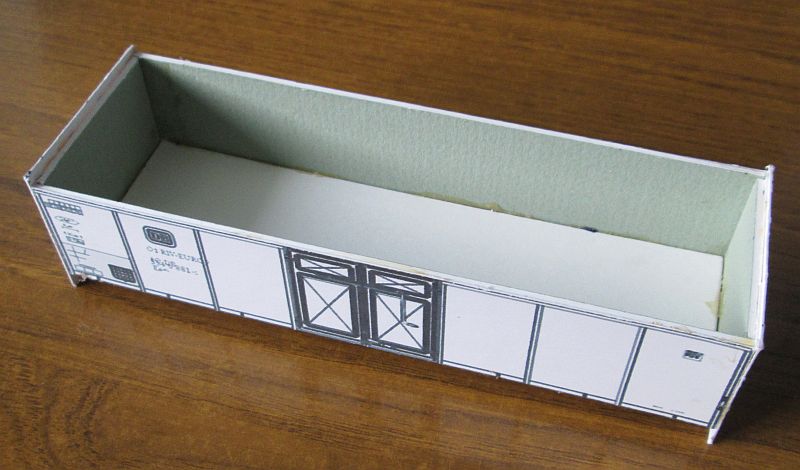
I've now added the bracing that run along the top of the wagon and also the vertical struts on the sides.
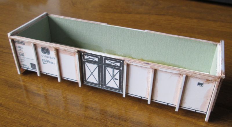
At the ends I've also added the bracing as well as triangular pieces to represent the hinges that the ends of the wagons pivot on when unloading. All of the struts used 0.60" by 0.60" plastic solvented onto the card - hence the discolouration of the card.
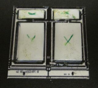
Making the doors proved easier than I expected. I cut rectangles of 40 thou plasticard 5mm x 10mm and 10mm by 15mm. I then drew diagonal lines on each rectangle and then using a file at a gentle angle filed along the edges to make a sloping edge. I then altered the angle and filed towards the centre thus removing some of the lines. I did the same for each side of the rectangles until the slightly domed shape that the doors show was formed. Each one is a matter of a minute or so. Then the plastic was stuck onto the card of another print out of the plan. After allowing the solvent to dry I scored two diagonal lines across each of the four panels to emphasise the shape. The complete door unit was cut out to produce the double doors as above.
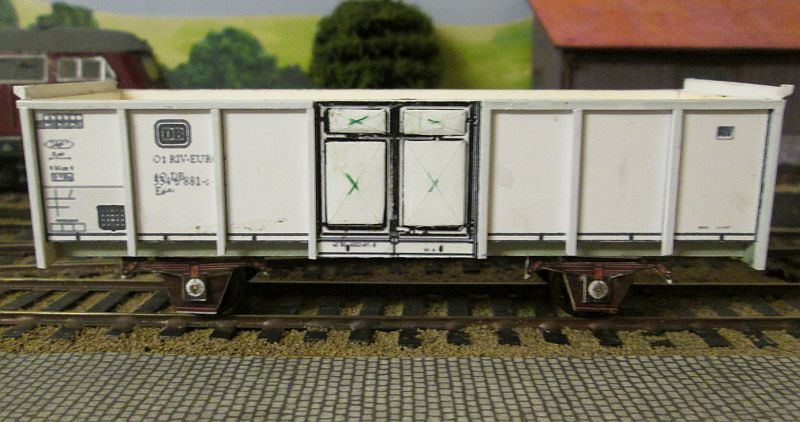
This photo shows the doors in place and also the wagon underframe details. The main frame is a strip of 4mm wide mounting card glued in place and strengthened under the body with more strips of card. The W irons and spring details come from the pdfs used on the other wagons.
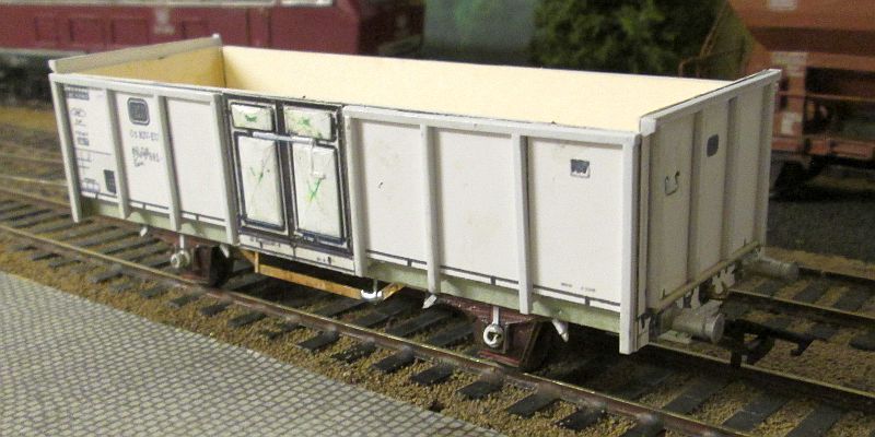
The wagon is now complete. Using plastic strip and rod I've added various small details such as the door locks at each end and on the side doors, axle boxes (from used ballpoint pen tubes), the strengthening blocks between the vertical struts and the underframe and the suspension points of the springs.
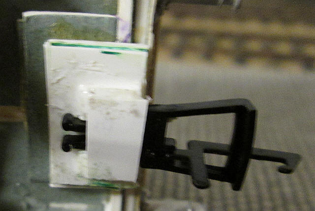
The couplings are Hornby plug-in ones mounted in a homemade NEM type pocket. These are made up out of layers of card an plastic attached under the buffer beam. The coupling hook is made out of metal so they can be uncoupled easily using a magnet on a stick.
The wagons have now been painted and the decals applied.
DB Klm 441 (former Rmms 33) 2 axle stake wagon
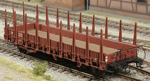
The DRG "Ulm" Rmms 33 Rungenwagen was built in huge numbers (nearly 13,000) from 1944 onwards and lasted in traffic into the 1990s. Originally they had wooden sides but these were replaced with steel ones. Many operated without stakes but I have decided to model mine with the steel stakes as in this O Scale model.
As far as possible the model was constructed from cardboard but I have also used plastic microstrip and T and U section profile for the details.
Having found a diagram of the timber bodied version on the Internet this was printed out the correct size for S Scale on thick mounting board cardboard.
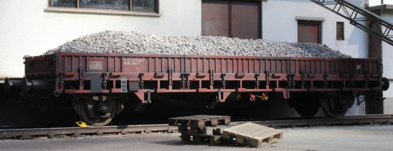
However, I wanted a model of one of the steel bodied wagons as in this photo....
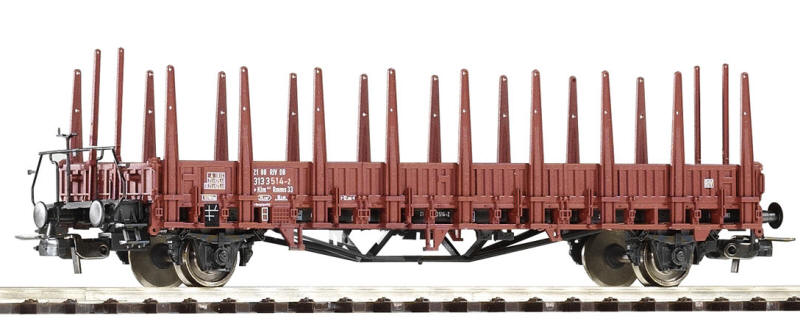
....or in this Piko HO scale model. The model has a brake platform.....
.....but I'm building one of those without a brake platform. ( A Marklin Gauge 1 model)
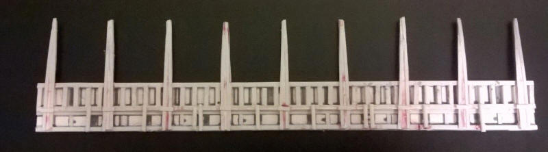
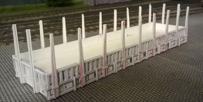
The stakes were made from 20 thou plastic cut to shape with narrow strips of 10 thou solvented to them to form the strengthening seen in the photos above. On the rear of the stakes I attached T section profiles to prevent the stakes warping.
In the photo above the wagon body is at the top whilst the underframe which has the supports for the stakes is at the bottom. I don't intend to cut out the gaps in the frame as this will weaken the model too much. When painted black the "gaps2 in the frame will not be obvious.
The sides and ends were then glued to a the floor and various strengthening pieces were added to lower frame to support it. The basic body is now complete.
The rocking w irons and wheels have been glued to the underside of the wagon. To get the correct height I need to add another layer of mounting card.
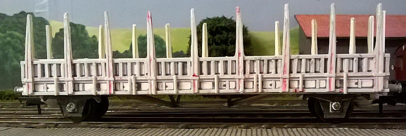
The wagon is now on its wheels and has also had the buffers added.
It became obvious over the next few days that the stakes, even laminated out of three layers would warp and also be brittle. I decided to strengthen them with a length of brass wire glued to the rear of the stakes with epoxy. A slot was cut into the inside of the wagon body and the wires pressed into this. When all the stakes had been strengthened I glued a strip of the card over the inside of the body to trap the wires in place. The epoxy on the rear of the stakes looks much the same as the back of the real stakes so it is actually an improvement.
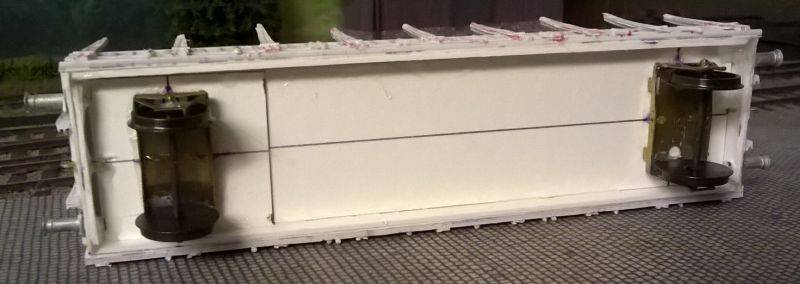
The strengthening struts under the body were cut and bent from six pieces of rail profile soldered to each other and secured to the body using small pieces of copper clad paxolin.
Seen from the side the strengthening struts give the appearance of solidity to the wagon. I've also added the W iron plates and springs cut from card and strengthened on the back with epoxy resin.
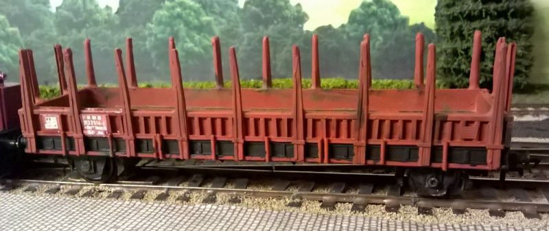
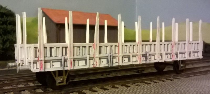
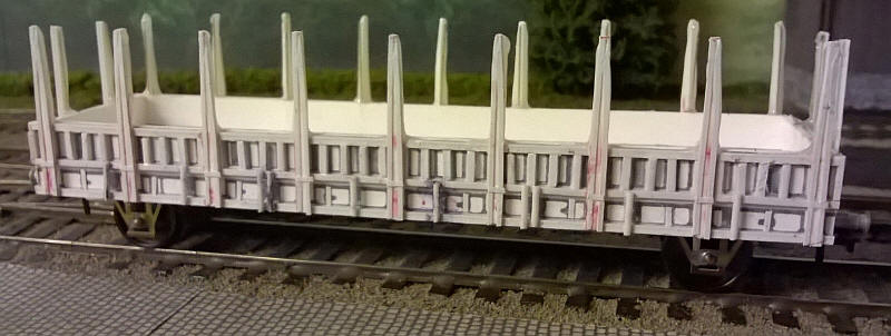
The model has now been painted, lettered and weathered. The lettering was taken from a photo of an O Scale model of this type of wagon and cropped and resized before printing out on paper.
I've also added brake shoes. These are etched nickel silver ones from the fret of a loco kit. They are mounted on wires soldered to the brass rocking and fixed w irons.
DB Cement silo wagon type UCS 908
For my next wagon, a Staubbehälterwagen or cement silo wagon, I'm going to use another pdf kit by Albrecht Pirling. After resizing the pages to S Scale they were printed out on thin card.
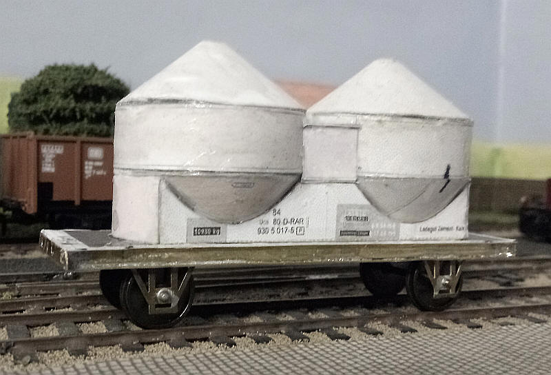
The photo shows a DB UCS 908 seen in 1980.
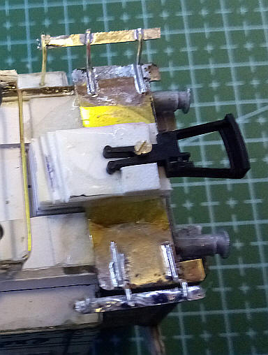
Fortunately some of the brass underframe kits I have can easily be modified to suit this vehicle. The underframe was originally intended for a 17' 6" wheelbase vehicle and comes with the usual rocking W iron units. The base plate has etched strips that fold up along the edges onto which are soldered the solebars and buffer beams. Being intended for the narrower British wagons the resulting width matches exactly the relatively narrow main frame of the silo wagon.
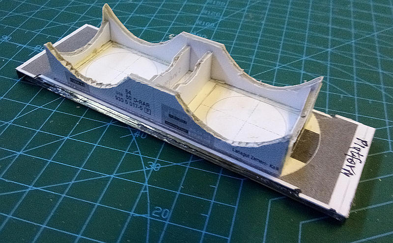
I've used the parts from the pdf printout to make the frame that supports the cylindrical silos. The thin card has been strengthened with mounting card and the base which is glued directly to the top of the brass underframe has been extended slightly to allow for a shunter's platform at one end of the wagon.
The next part of the construction is likely to be the most demanding; building the two cylindrical silos which taper both at the top and bottom to form cones.
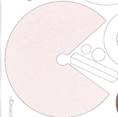
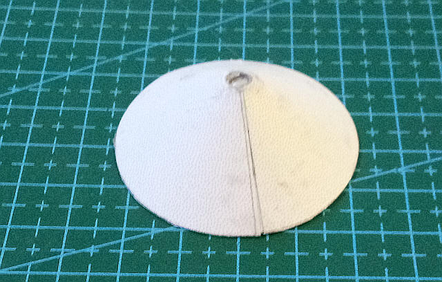
The image above shows top of the silo from the pdf which after cutting out is curved to form the pointed top. The bottom of the silo is similar.
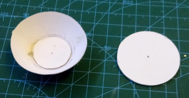
The images on the left show the bottom section after folding and with the circular base (from mounting card already in place. The disc is 40mm wide and cut with a cutting compass.
The image on the right shows the assembly after gluing the disc in place with epoxy resin. This was also spread over the entire inner surface of the cone.
The top cone section.
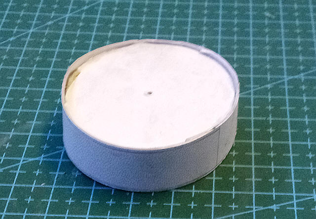
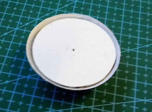
The middle cylindrical section. This has two discs 45mm in diameter glued at the top and bottom and separated by two strips of mounting card at right angles to each other.
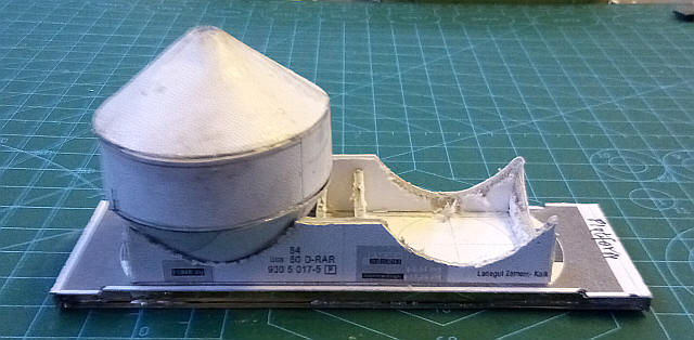
The three parts of the first silo have been glued together and pleasingly the top of the cone is at exactly the correct height.
Both silos are temporarily in place together with the wheelsets.
The central section between the two silos and the lower ends have now been added together with a lot of epoxy used as a filler.
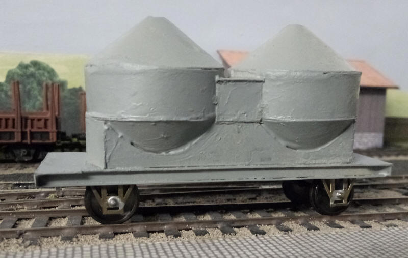
As I expected the first undercoat reveals numerous places where more filler is needed and some rubbing down with a fibre glass pen to smooth the surface imperfections. Although it appears in the photo that the top of the cones are not at the same height this is an optical illusion.
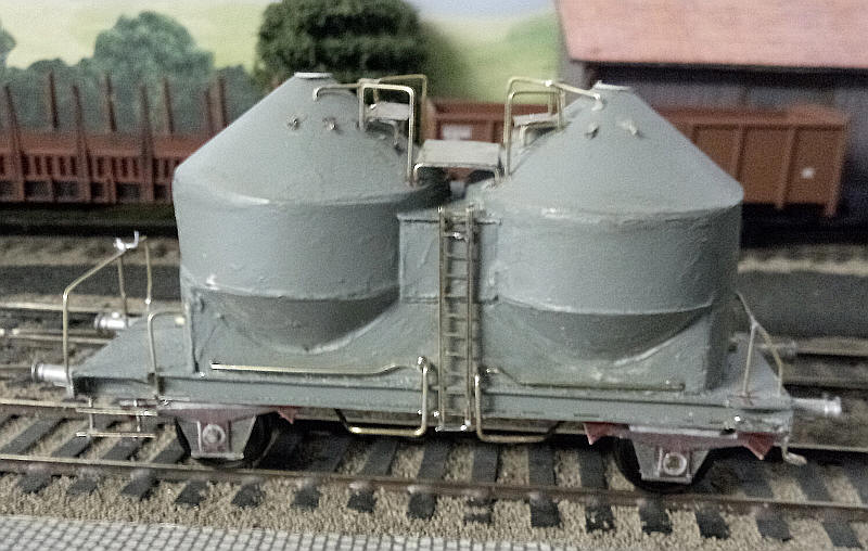
Considerable work is needed with this wagon to provide the numerous handrails, ladders and pipes.
A variety of thicknesses of brass wire have been bent to shape and secured in holes drilled in the card.
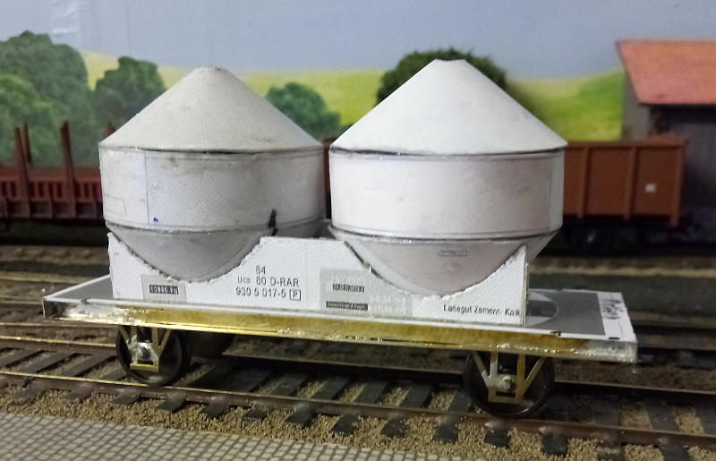
The model in its completed state after painting in correct shade of very light grey.
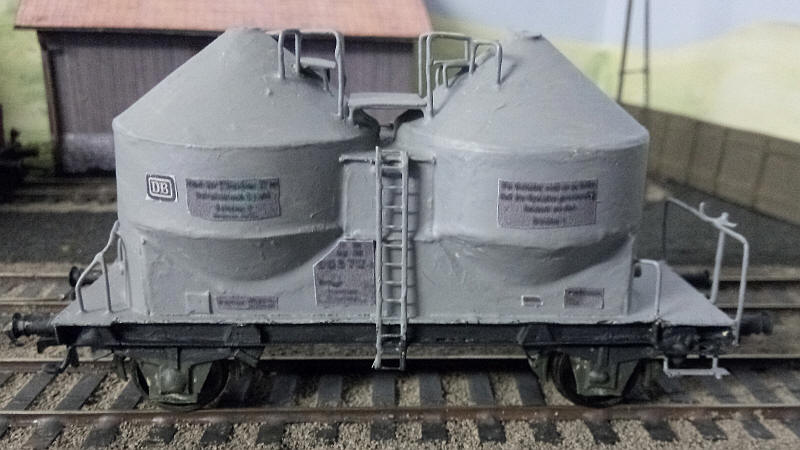
In the absence of any suitable transfers for the lettering I found photos on the Internet of these types of wagons and printed them out at the correct size. The relevant sections of text have been glued onto the wagon. The photo makes the edges appear more prominent than in real life.
DB Freight train conductor's van Pwghs54

The Pwghs 54 vans were built to provide luggage and parcels accommodation for semi fast trains and had through piping for steam and electric train heating. They were also to be found on freight trains especially on branch lines where the conductor looked after parcels traffic for intermediate stations. T
This model followed much the same construction methods as the Gs212 van described above. The major differences for the body were the inclusion of windows for the compartment used for the office of the conductor and the adjacent toilet as well as a recessed door giving access to the shunter's platform.
The chassis has an extended underframe for the shunter's platform. The step supports were soldered to small pieces of brass sheet glued under the platform. Wire handrails completed the model.
The photo below shows one of the last Pwghs 54 vans still in use on the branch to Ebern in 1982.

Fuel tankers
One type of wagon which I feel is necessary for the layout is an oil or petrol tanker. Two suitable prototypes appealed to me so I decided to build one of each


Diagrams for both types can be found in an old MIBA Spezial issue.

Obviously the method of constructing the tank with its domed end has to be decided on. After a lot of thought I cut lengths of thin card and wrapped these around an old broom handle. It needed about 20 layers before the correct diameter was achieved.
The domed ends use a slightly unusual technique. Most small aerosol cans have a recessed dome end at the bottom of the can. A layer of Clingfilm was pressed into this and then Milliput filler was mixed well and pressed into this filling the entire "dome". Once set (after a few hours) the Clingfilm can be used to lift out the solid Milliput giving a perfect dome. A piece of card had a hole cut in it and this was used to draw a circle on the curved surface of the Milliput. A very fine fret saw blade was then used to cut along this line to produce the domed end of the tank. This was the secured to the end of the card tube with epoxy. Any gaps were then filled with filler and the joints filled smooth.

The completed tank has been sprayed with a primer. There are one or two blemishes and places that need a little filler but otherwise the tank is acceptable.


To produce the chassis I decided to use components from a British 16' 6" wheelbase etched brass wagon underframe kit, but heavily modified to allow both an extended wheelbase and also to have plenty of "fresh air" under the tank and also at one of the ends. A further requirement was to have the shunter's platform at one end. To do this I used the W irons and the rocking units as normal but removed sections of what would have been the floor of a British wagon to give open spaces. On the etch there are plenty of suitable lengths of brass strip which can be used to produce the extended solebars and the L shaped frames in between the w irons. There is scope for adding more bracing and detailing on the underframe but the basic underframe is now complete and rolls satisfactorily

The model has now had a representation of the brake details added to the open centre section of the chassis. These are based on photos and diagrams of this type of wagon and utilise nickel silver strip for the two longitudinal beams along the centre of the chassis. Brass strip, wire and short section of tube make up the complex of pipe work . It's a fairly close representation of the real thing but is not intended to be accurate, rather something that fills the gap underneath the tank. The brakes are made from U shaped lengths of wire soldered to the W iron frames. The brake blocks are from spare S Scale loco etchings.

The tank has now been added to the chassis. It sits on saddles made from grey board and is secured with two part epoxy. Still to be added are the diagonal sides of the saddles.

The sides of the saddles have been added . The shunter's platform has received its railings which are at different heights to each other. I've use lengths of square brass section cut at the corners and bent into a U shape. These were soldered in place to the solebar frames and bufferbeams with the joint corners being filled with solder. Some accurate cutting was needed for this and pleasingly everything fitted first time.

The next major step in construction is adding the various parts on the tank. The large dome shape is from a short length of plastic tube from a marker pen filled with epoxy to give the rounded top. Its held securely in place with a length of wire passed through a hole in the cardboard tank. The walkways are strips of nickel silver soldered to lengths of wire passed through holes drilled in the tank side. The ladder is a 4mm scale etched signal ladder strengthened with brass wire.

A few more details have been added, including a brass panel which will have the wagon's data panel stuck on it.

i've sprayed the model all-over black and weathered the model with various shades of brown and grey. The paint hides a lot of the constructional mistakes!
The Esso logo is a print out from the pdf of the Miba book. Being a pdf it is easy to do a screen shot, rezize the image and print out onto white paper. The wagon's date panel is similarly obtained from the book - the photos of the prototype model earlier in this section was resized to fit on the brass data panel board.