An S Scale DB V100 diesel locomotive
On 31st July 1980 211092 is seen at Wilhelmshaven.
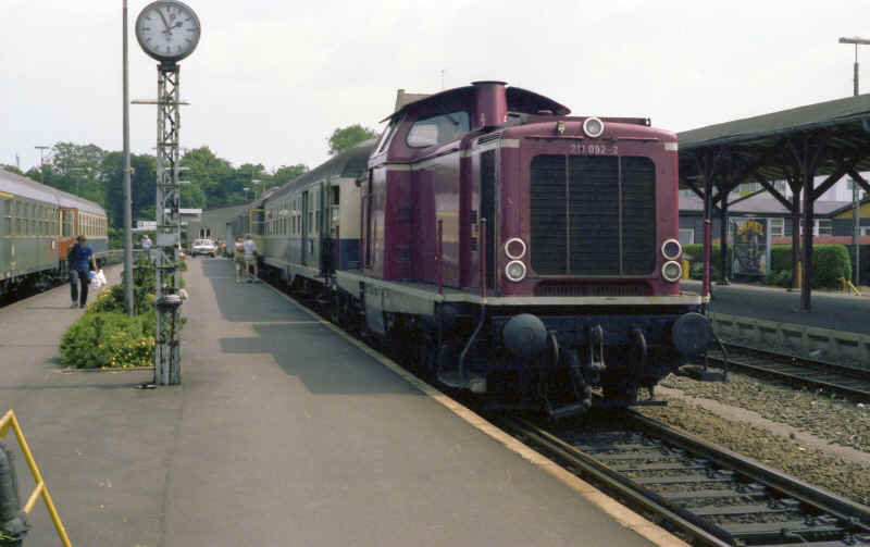
Having built the body of a six wheel Deutsche Bundesbahn 'Umbauwagen' the next stage was to find out if I could build a suitable locomotive to power a train of these models. After various unsuccessful experiments with modified Airfix tender drive units I finally discovered the BEC tram car dive units. The DB V100 (later BR211 and BR212 classes) have a bogie wheelbase of 2.20 metres which in S Scale equates to 34.375mm. BEC produce a 34mm wheelbase tramcar drive. A phone call to BEC produced the offer of building these with O Scale axles and Romford 14mm disc wheels. The V100s had 950mm diameter wheels (14.84mm in S Scale) so I could hardly have got any closer. A week later I received the two motor bogies for less than £50. Knowing that I was intending to use them for a Bo-Bo chassis BEC had fitted the bogies with a pivot mounting bracket above the motor. Also included were press studs and a cast bogie pivot bar.
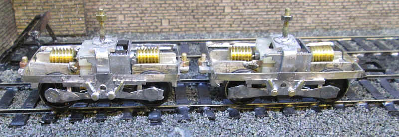
The V100's chassis
The first task was to slide the Romford wheels on their axles out to the correct gauge for S Scale. I gently levered these wheels out using a screwdriver and small pliers. Once the pickup wires were adjusted the bogies ran smoothly, if a little noisily. The excess axle lengths were cut off with side cutters.
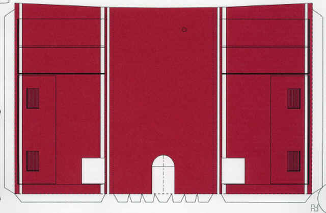
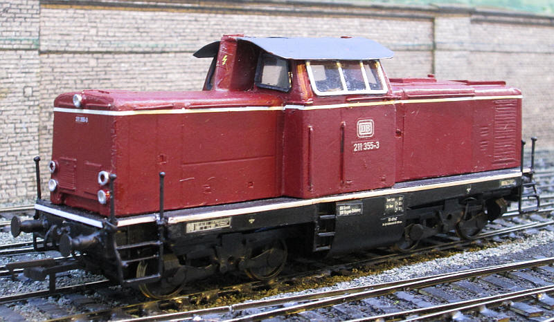
Scale drawing of the DB V100
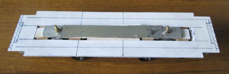
Rather than use the press studs as pivots I decided to solder 8 BA bolts onto the bogie pivot brackets. The cast metal pivot mounts had 1/16th top hat bearings soldered into the hole intended for the press stud. These were then reamed out to provide a firm location point for the bolts. A strip of scrap nickel silver was soldered in place to give the correct bogie centre distance on the bogie pivot bar
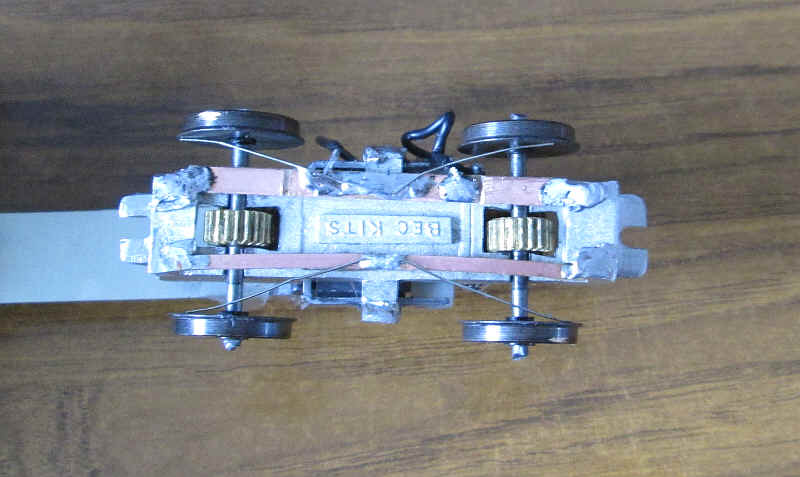
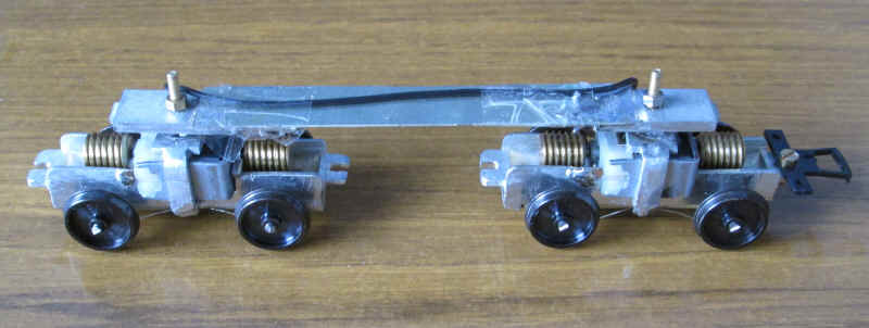
The bogies already have pickups in place secured to copper clad paxolin strips. One of these strips is live to the chassis block with one of the motor terminals soldered direct to the cast metal chassis. This means that when the bogies are bolted to the pivot bar this will be live, so the bogies must be the same way round to avoid a short circuit.
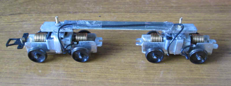
I then soldered a length of wire linking the insulated pickups of each bogie. This was secured to the nickel silver with sellotape and ensures that the bogies can't rotate through 180 degrees. A coupling bar was temporarily bolted in place on one bogie and testing commenced. Performance is excellent with very slow running possible. Even without additional weight the 'locomotive' comfortably pulls a rake of four Midland Railway six wheel coaches on Halifax Midland.
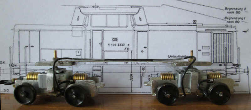
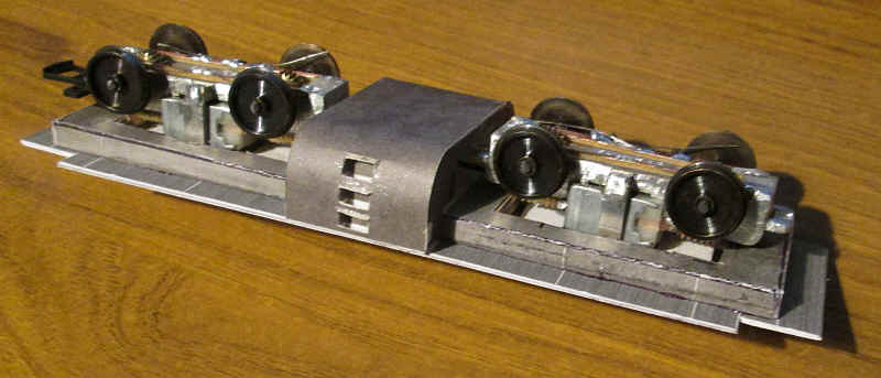
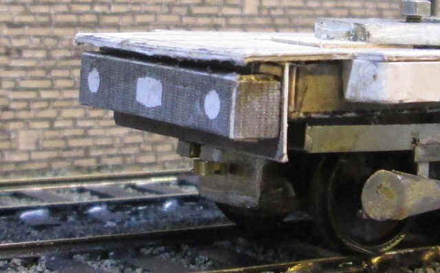
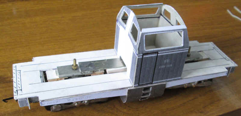
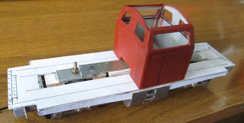
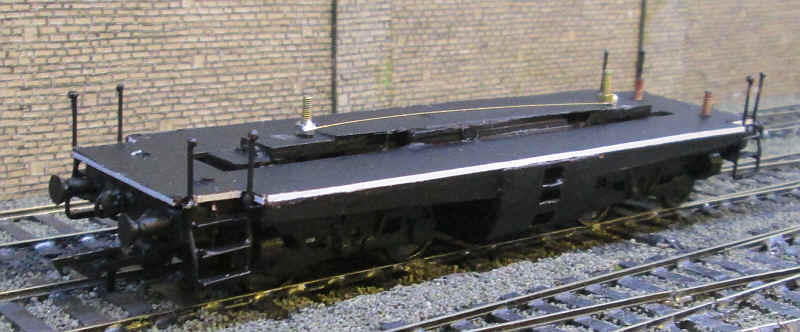
This photograph shows how the chassis will fit in the model
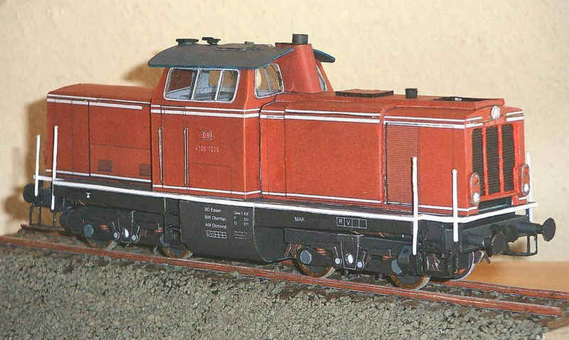
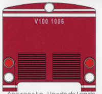
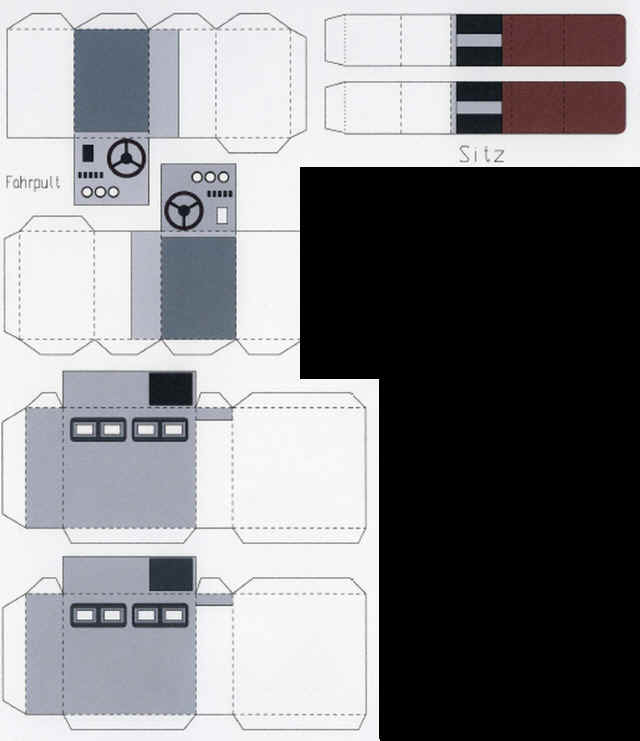
As with the 'Umbauwagen' coach I intend to use the resized card pdf kit by Albrecht Pirling as the basis of my model. The photograph shows one of these assembled O scale models. The original plan was to build the cab using brass for strength around the windows but for the rest of the model to be in card. In the end even the cab was made of card.
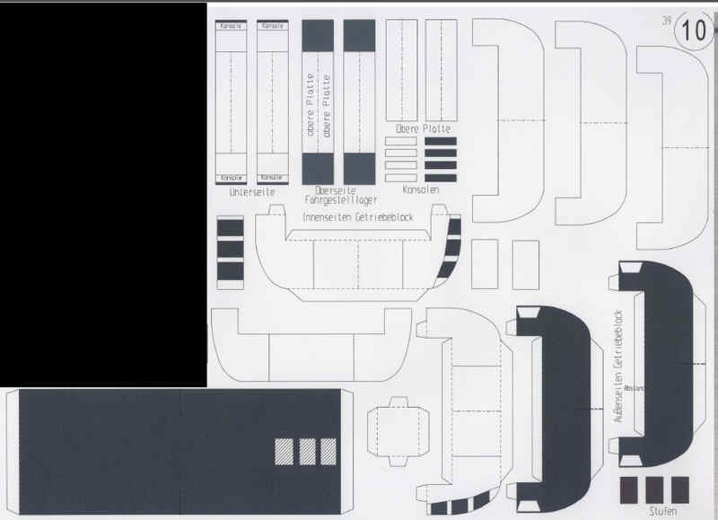
Construction starts with the assembly of the running plate which is assembled out of four overlapping pieces of card cut from the pdfs seen below.
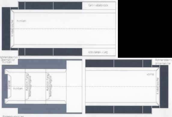
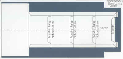
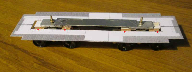
The resulting rectangle has recesses at cut out for the steps at each corner of the locomotive. A strip about 20mm wide was cut out of the centre pf the running plate to allow it to drop in place around the bogie pivot bar. To get the running plate at the correct height, pieces of card were glued underneath the metal to support the running plate. A strip about 20mm wide was cut out of the running plate to allow it to drop in place around the metal bogie pivot bar. To get the running plate at the correct height pieces of card were glued underneath the metal to support the running plate. These can be seen by the red dots.
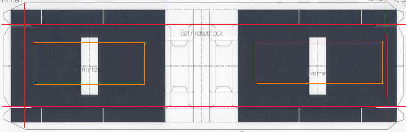
The next stage of construction is to add the main underframe section to the under side of the running plate. This section of the pdf kit is seen above. The card is folded to make what is effectively a box without a lid. As well as folding the card along the edges to make tabs the card is also folded along where the red lines are marked. The card within the orange rectangles is cut away to five space for the bogies to rotate.
Once folded into shape three layers of thick card were glued inside the open box so that when it is glued in place on the underside of the running plate there is a solid mass of card which makes the running plate and frame absolutely rigid. In actual fact it is probably as strong as an equivalent metal sheet structure would be.
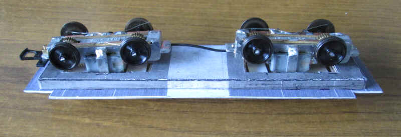
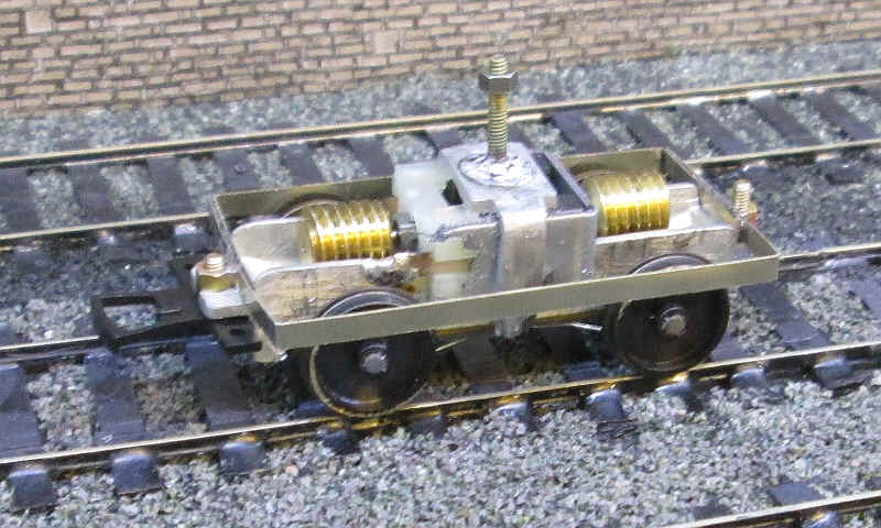
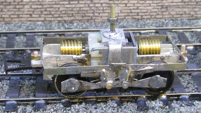
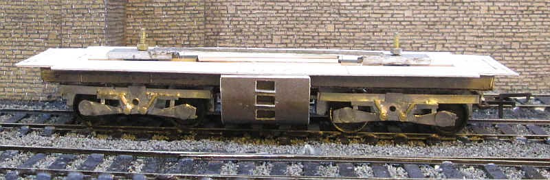
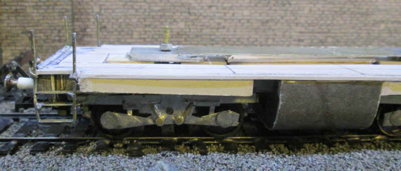
The assembled chassis and frame/running plate. A thin wire links the live terminals of the motor whilst the negative terminals are live through the metal bogie pivot bar.
I also decided to add a further layer of thin card to the top of the running plate so there are now three layers laminated together.
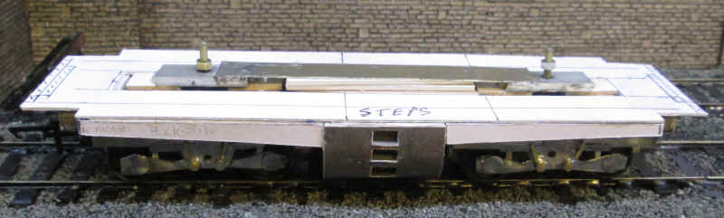
The next stage of assembly is to fabricate the fuel tank which sits under the cab. This is quite an intricate unit measuring about 30mm x 50mm x 20mm and is made up out of about 15 parts.
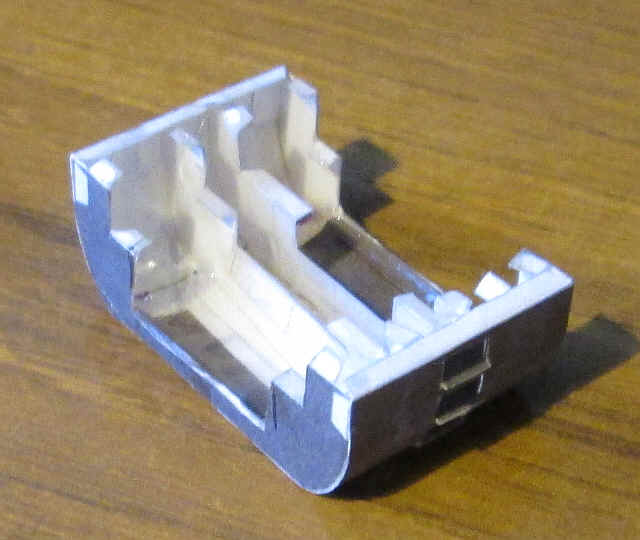
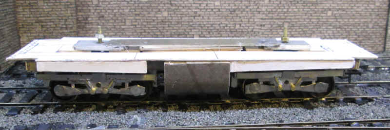
The completed fuel tank with steps (on one side only) is ready to be clipped onto the underframe. I had to modify the crosspieces to allow the bogie ends to rotate and for the wire between to bogies to be feed through. The inside of the card was given a layer of Devcon epoxy to strengthen it.
The fuel tank is designed to fit in place around the underframe and when assembled clipped into place perfectly, not needing to be glued in place.
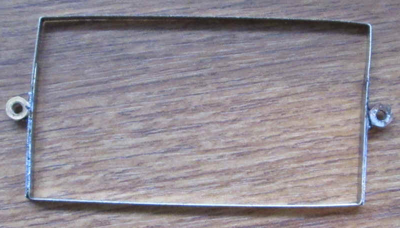
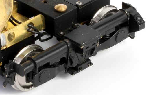
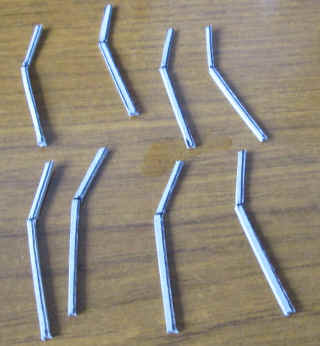
I decided that the easiest way to make the bogie sides was to make a 'wrap round' frame from nickel silver strip with two nuts soldered at either end as seen above. The frame will be secured in place using bolts passed through the slots that at either end of the motor bogies.
The bogie with the frame bolted in place.
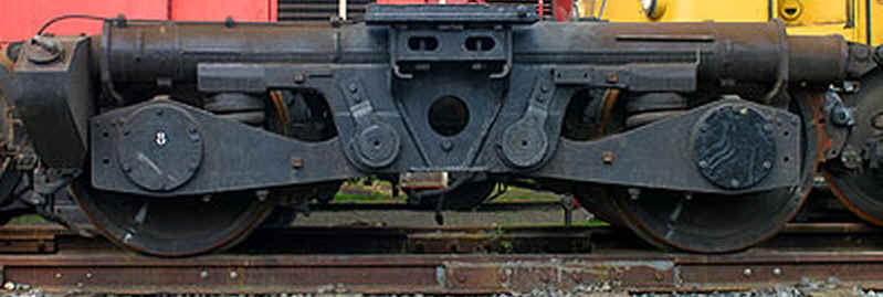
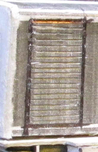
This is a view of a V100 bogie and shows the relatively simple construction. The tube at the top appears to be the brake cylinder whilst the sandbox is on the left (outer end of the bogie).
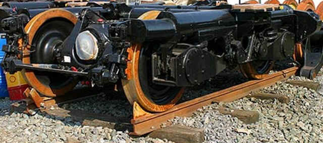
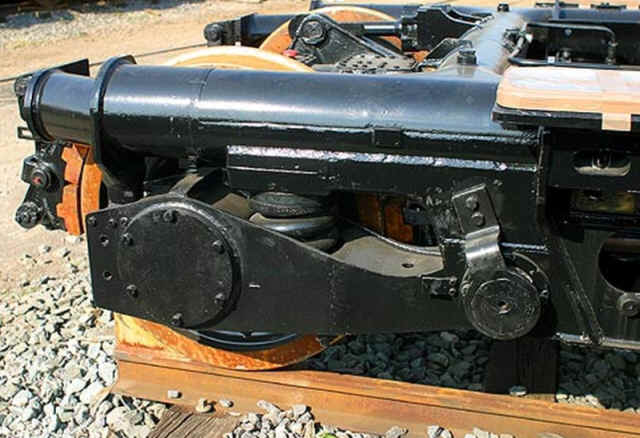
Two close up views of a preserved V100 bogie.
An interpretation of the bogie for an O gauge V100
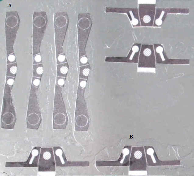
The next stage in construction of the bogie side frames was to cut out the various from a sheet of tinplate. The templates from the card "kit" where stuck in place with PVA glue and then cut out using a sharp pair of scissors.
The bogie side frames are assembled from the two different shaped pieces of tinplate (A and B). Part B is soldered onto part A with the "three circles" overlapping each other. The large central hole is then drilled out.
This part is then soldered onto the 'wrap round' frame as in the photo above. The V100 has very prominent axle box covers and these are easily represented by circles of tinplate that have been cut using a two hole paper punch. These are soldered in place. The next stage is to solder the heads of two 10BA bolts to represent what I think are pivot points for the axlebox holders. The bolt threads are cut off and the bolt heads are filed smooth. Two short lengths of brass wire are soldered in place pointing diagonally away from the bolt heads.
The two bogies have now almost been completed. Some small vertical brass strips have been added to represent the springs linking the bogie frame to the axleboxes. The rear of the frames and axlebox supports have been strengthened with brass wire soldered in place.
With the bogies in place it's beginning to look like a Bo Bo diesel. Performance is smooth although a little noisier than I'd like whilst haulage even is adequate pulling three of my heavy bogie coaches.
The next stage is to add the valances to the footplate. These are tapered strips of card which I have strengthened with three layers of 1mm thick card glued to the underside of the running plate. The valences are "handed" with one having a gap for the steps which are in different positions due the asymmetrical nature of the V100.
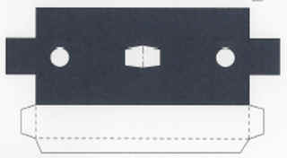
A cruelly enlarged view of the bufferbeam. A backing plate is mounted to the locomotive frame and onto this is glued a cuboid formed from card folded up from this net:
To make the bufferbeam strong enough strips of thick card were glued inside the cuboid before sealing the ends. The basic chassis is now complete apart from adding details such as sand boxes, air tanks, buffers, couplings, the shunter's steps at each corner and the second set of cab steps. I'll add these later to avoid damaging these relatively delicate parts during the building of the body.
The V100's body
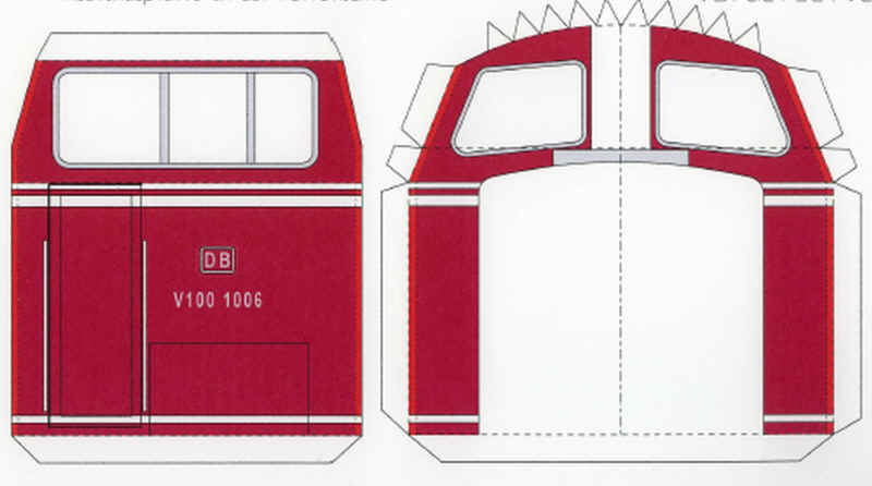
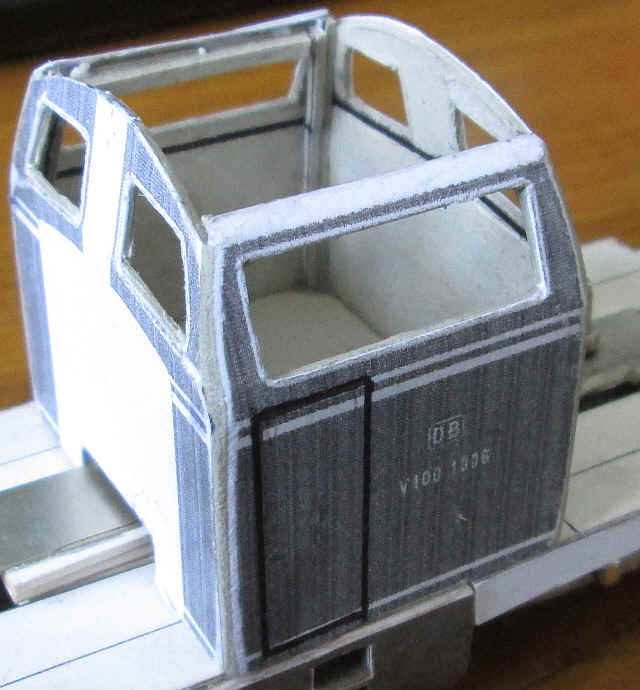
The cab of the V100 is a complex affair with bends and curves in several planes so to a large extent this is another 'make or break' stage of construction. The two parts shown above are from the pdf. Glazing these windows and building the cabs with sufficient strength is difficult but here the power of the Internet came to my aid. Norman Gorn, a Canadian, has built one of these models to an exceptionally high standard and presented his work on a thread of the Kartonist.de website. Sadly this website has now closed but I used Norman's methods as decribed below
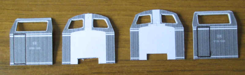
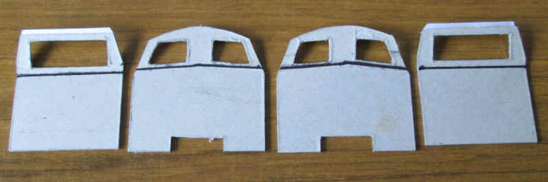
To build the cap I glued the thin printed card onto much thicker card - slightly over 1mm thick. The cab sides and fronts were cut out leaving just the tabs at the top of the sides to secure the roof.
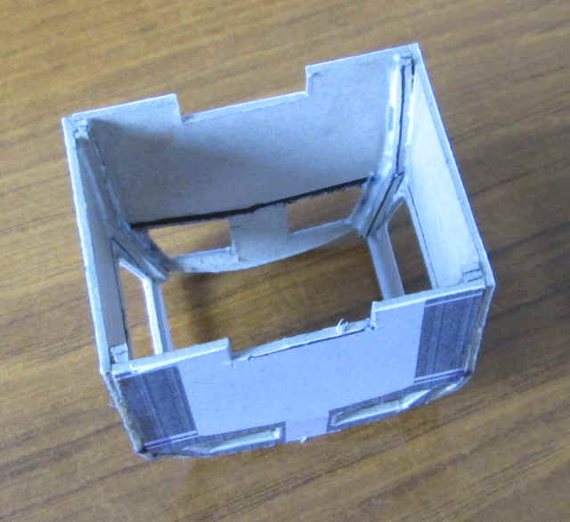
The next task is to cut out the inside of the window apertures. To do this, and get a round corner, I made a pin prick with an old pair of compasses about half a millimetre away from the corners of the windows. A small jewellers' screwdriver was passed through the hole enlarging it. The card was then cut to give the window openings. As can be seen in the photos the outer window frames remain in place. To clear the bogie mounting bar I also needed to cut a slot in the two cab ends. The outline for the door openings were pressed into the card with a black biro.
To get the correct shape of the cab the upper part of the windows need folding precisely. To do this I drew black lines on the rear of the parts with a biro and then continued scoring. Then using a steel ruler and a pair of 'tweezer pliers' I bent in the card at the top.
The cab was assembled using Bostik adhesive on the butt joints with the cab sides overlapping the fronts. Once again the parts all aligned perfectly.
One of the problems with kits such as this one is that it is hard to get round or complex corners using card. Norman Gorn's solution was to cut strips of thick card to fit inside the corners of the cab and then to trim and file the corners until they are round.
I cut some strips from thick card shaped as above and then...
....glued to in each corner using PVA glue.
After leaving the PVA glue to harden I gentle files the corners to give a round edge. This was followed by a coat of PVA and then rubbing over the sealed corners with a fibre glass pen. I also strengthened the very weak top edge of the cab side windows with two strips of 1mm thick card,
The completed basic cab unit showing the rounded corners which after applying a coat of red primer appear to be reasonably smooth.
One aspect of the model's construction that has worried me is the cab glazing. Norman Gorn's solution, which worked well in O Scale, was tried first. He stuck double sided sellotape behind the cab windows, leaving the backing paper in place. Then he cut out the window apertures. After peeling back the backing paper he pressed some clear plastic glazing onto the sellotape and cut around the outer edge of the window frames. The entire window frame and glazing was then glued in place on the cab.
I tried this, but with the much smaller amount of sellotape on the S Scale width frames there wasn't really enough adhesion and the frame wasn't securely stuck in place.
For the second attempt the window frame was cut out by first removing the window openings and then cutting around the exterior of the frame. I then spread a little PVA on the card and laid it onto the glazing. This won't hold it in place permanently, but once dry I spread a very thin smear of two part epoxy resin around the outer edge of the frame thus bonding glazing and card frame together. This is a task best done under magnification and with a steady hand to avoid getting epoxy on the glazing.
Once the epoxy has set the frame can be fixed in place over the openings in the cab sides -remember that the outline of the window frame was left in place when cutting out the cab sides. I won't add the windows until the model is painted.
Construction now moves onto the two hoods at either side of the centre cab. The first one to be tackled is the shorter one which contained things like auxiliary equipment and the steam heating boiler. The pdf kit is designed for this to be built from a single wrap around piece of card with a bonnet end. All corners would almost inevitably be right angles. However, following the example of Norman Gorn it is possible to build the hoods much closer to the real thing with round corners.
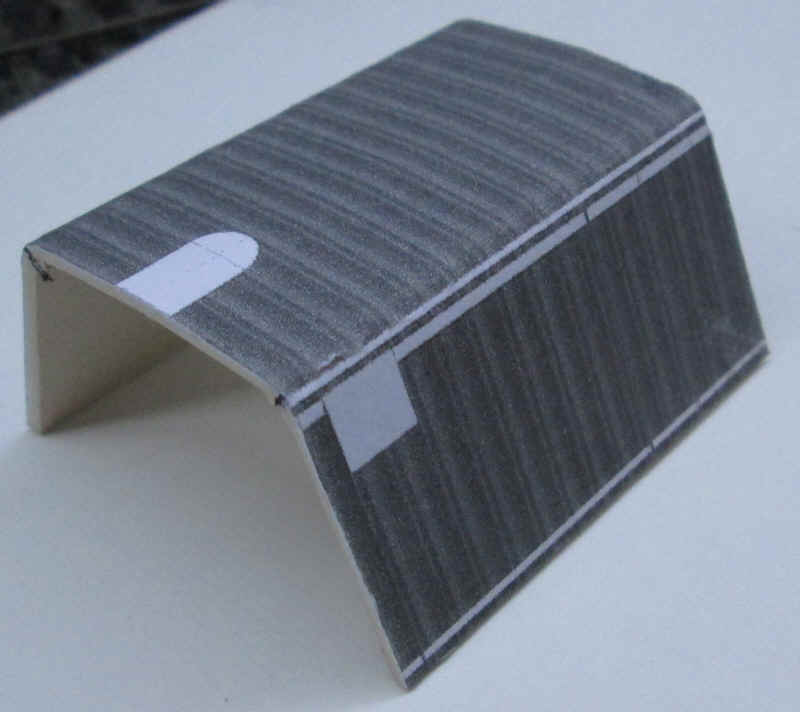
The first step is to glue the hood sides and top to a piece of very thick card. Once completely dry it's time to start to bend the angle. On the underside of the hood I scored two lines exactly in line with the top white line. After repeating this process several times I rescored the line with a firmer point and then gently began to bend the corners. Then I opened the card out flat and using a cross head screwdriver scored a deep indentation into the thick backing layer. This makes it possible to bend the sides at right angles to the top but introduces a perfect curve without any cracking of the outer layer of the card. Finally, I bent the hood top with my fingers to get a gentle curve that will match the profile of the hood ends.
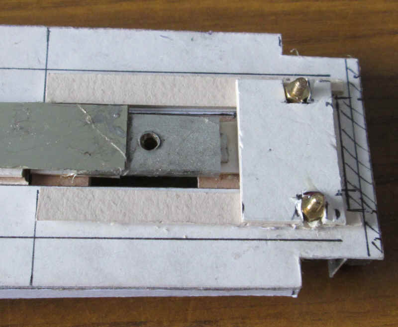
The hoods and cabs will need to be built as a complete unit so that they can be lifted off the frame to allow access to the bogie pivot bolts. To do this I decided to pass bolts through the loco's main frame and secure the underside of the body with some captive nuts. The photo above shows how this will be done.
First of all I cut a U shaped piece of thick card (creamy in the photo) that will form the bottom of the hood. The hood sides will be glued to this later on. Two holes were drilled through the card and the loco frames with nuts and bolts securing it in place. The nuts need to be retained in place so the next job is to position another piece of card with slots cut in it to prevent the nuts rotating. Finally another piece of card was secured in place above this (secured with a little two part epoxy resin) to clamp the nuts in place.
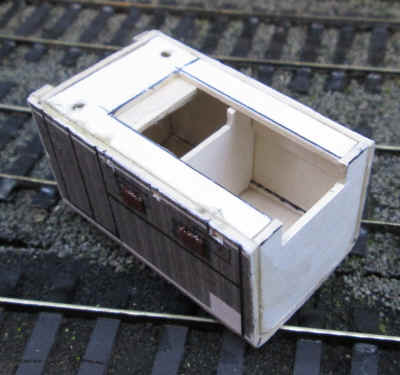
These two photo shows the hood after it's been assembled. Four cross profile pieces were cut to the exact width of the inside of the folded up bonnet. Two of these were fitted at the front of the bonnet before the printed front was glued in place. The two layers allow the corners to be rounded in the same way as the cab corners. Another profile was added in the center of the hood and the fourth at the rear - this will later be glued onto the cab front. Various strengthening pieces were added inside the hood and then the hood base (complete with captive nuts) was glued flush with the bottom of the hood sides. I also cut some rectangular holes through the outer layer of the hood sides to represent what appear to be securing points for one of the opening panels.
The short hood of the V100 has various ventilation louvres fitted and I decided to represent these with plastic microrod secured to the card with solvent.
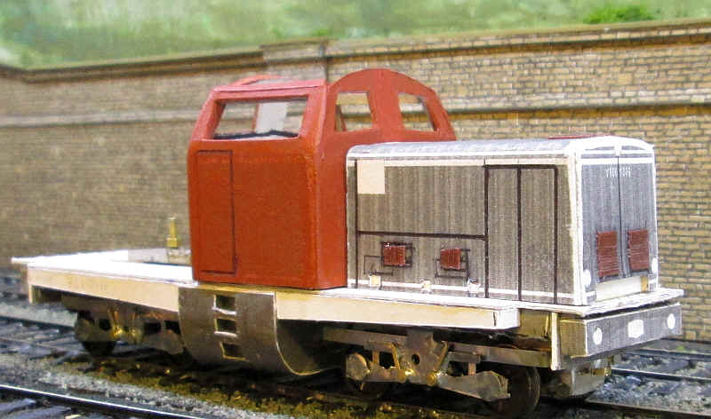
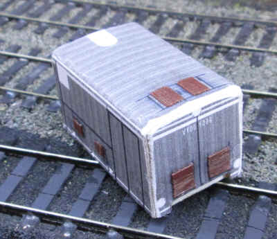
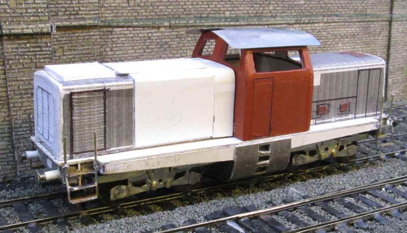
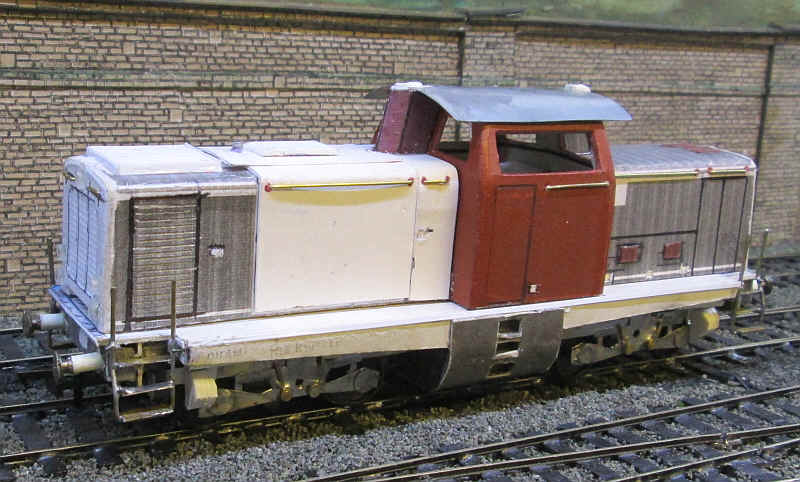
The model is now beginning to look a little like the V100 although that cab looks slightly too high.
Moving on to the next stage the larger hood has been built almost in the same way as the small one. I've also cut a millimetre off the base of the cab which lowers it to the correct height in proportion to the hoods. The second hood contained the motor so there are a lot more grills to be made at this end.
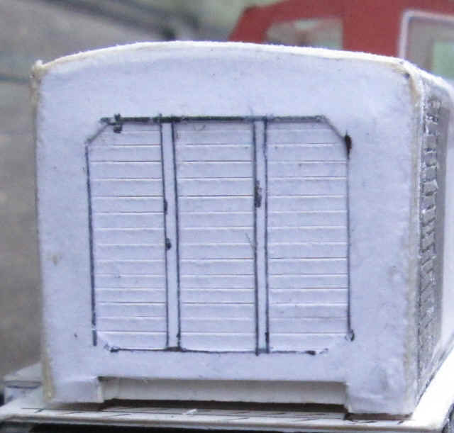
The one on the front is made by making horizontal cuts through a piece of card and then glue this onto a backing sheet. This is then glued with PVA behind the front end of the hood. The grills on the side of the hood were simply cut into the outer card layer with a scalpel and a line was scored around the outline with a biro.
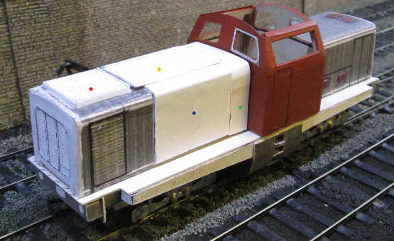
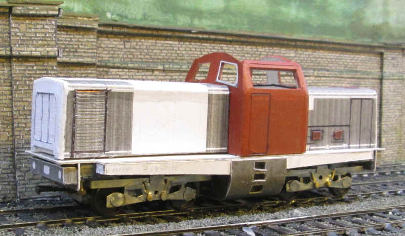
This photo shows another few parts added. Firstly, there's a broad 'wrapper' (blue dot) around the hood which doesn't quite reach the footplate as I think in real life it is lifted off the hood in the maintenance depots. Behind this is a narrower 'wrapper ' (green dot) which does reach the footplate. These are simply made out of thick card bent to shape and attached to the inner hood.
Moving to the front of the hood I've made a representation of the air intake for the motor (red dot). This is one of the various types fitted to the V100 and is a piece of card cut with strips to represent the slats. The edging to this is made up out of plastic strip which, on the front and rear edges has been scraped away to follow the curved profile of the hood. Finally there is a thin piece of card (yellow dot) which extends longitudinally along the top of the hood.
One of the items that adds a lot to a model locomotive's appearance are its buffers. The ones on the V100 are simple tube like structures. I drilled holes into the buffer beams (remember that these are made up from a card box inside of which there are multiple layers of thick card) and pressed into the holes lengths of plastic tubing. The buffer heads are Alan Gibson metal turnings with a disc of tinplate soldered onto the buffer head,
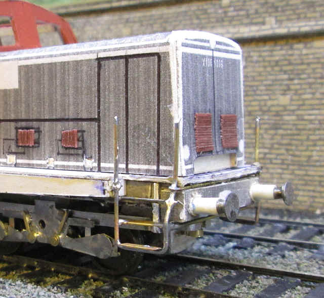
Now for one of the jobs I've been dreading: building the shunters' steps at the corners of the locomotives. These have been fabricated out if various pieces of brass wire and bras strip. They are held in place by thin brass wires that are buried within or hidden above and below the buffer beam. It's not a particularly neat job as my skills aren't particularly good at this sort of work but, once painted, I'm sure it will look reasonable enough.
Things have progressed a little further. Both ends now have the shunters' steps and handrails. To ensure these are held firmly in place the top step extends under the running plate and is held in place with two part epoxy resin, whilst the brass wires that pass above and below the bufferbeam are also secured in the same way.
I decided that using card for the roof would be a recipe for disaster with bent corners, so the card part was used as a template to cut out a piece from sheet tinplate. This is bent to shape and a thick piece of card is glued underneath to act as a means of locating the roof correctly within the cab ends and sides.
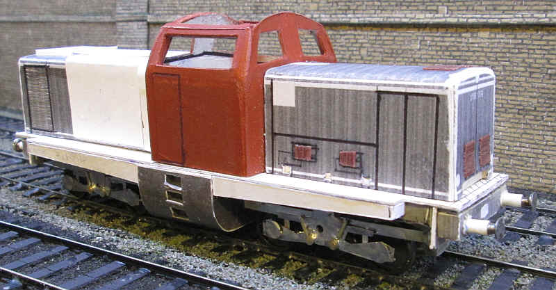
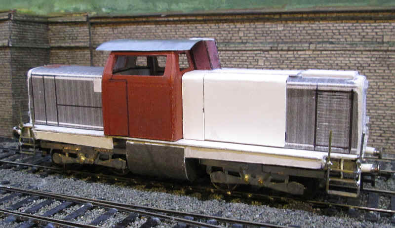
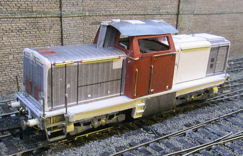
To my surprise the models is really looking like a Deutsche Bundesbahn V100.
It's now largely down to adding detail parts from now on. Here I've added the three headlights and two tail lights at one end. These are simply slivers of biro tube secured in place with a little two part epoxy resin adhesive.
There are exhaust outlets at either end of the cab. These are simple card wrappers which are folded to shape.
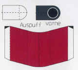
After folding to shape and gluing the top piece in place I reinforced them with layers of thick card inside the wrappers and then filled gaps with two part epoxy resin and fastened them in place on the cab fronts using the same adhesive. The metal cab roof that I'd cut to shape earlier has slots at both ends to accommodate the exhausts.
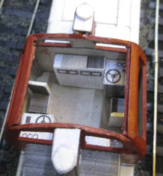
The pdf comes with a fully detailed cab interior. These are simply folded up and glued in place as in the photo below.
One of the distinctive features of the V100s was the broad white band along the edge of the running plate. I was concerned that it would be difficult to represent this neatly and eventually came up with the idea of using 15 thou by 40 thou microstrip fastened to the cardboard edges with copious amounts of solvent in the way that I have done on my Midland Railway panelled coaches. The photo below shows chassis after applying these strips. After painting I will use a small file to scrape off the paint and hopefully this will leave a neat line.
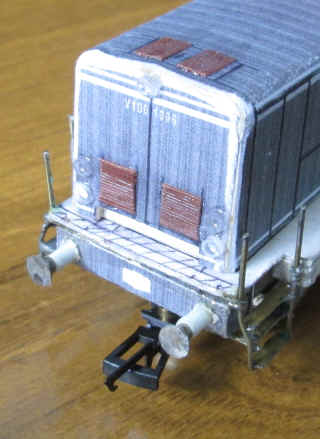
A little more progress has been made: airtanks under the running plate and sandboxes fitted to the bogies. These were made from plastic tubing and layered plasticard cut to shape respectively. The numerous handrail made from 0.7mm brass wire have also been fitted. Not visible in the photograph are the slivers of plasticard that have been glued inside the small square openings in various places on the door panels.
Looking on the other side of the locomotive the cab steps by the side of the fuel tank have been added and are made from plasticard. The bufferbeam now has a coupling hook and four air pipes and the remaining handrails on the cab have been added including the really tricky wrap round ones on the corners. The model is basically complete and ready for painting.
I'd been concerned how I was going to get that characteristic V100 white edge to the running plate until I hit on the idea of using microstrip. The results after painting can be seen below.
Once I'd sprayed the bogies and chassis matt black I simply scraped off the paint from the plastic with a scalpel giving an absolutely straight edge, including the tricky areas around the end steps. One alteration I have made is to link the two pivot point nuts with a piece of fine brass wire to make the current connection between the bogies more secure.
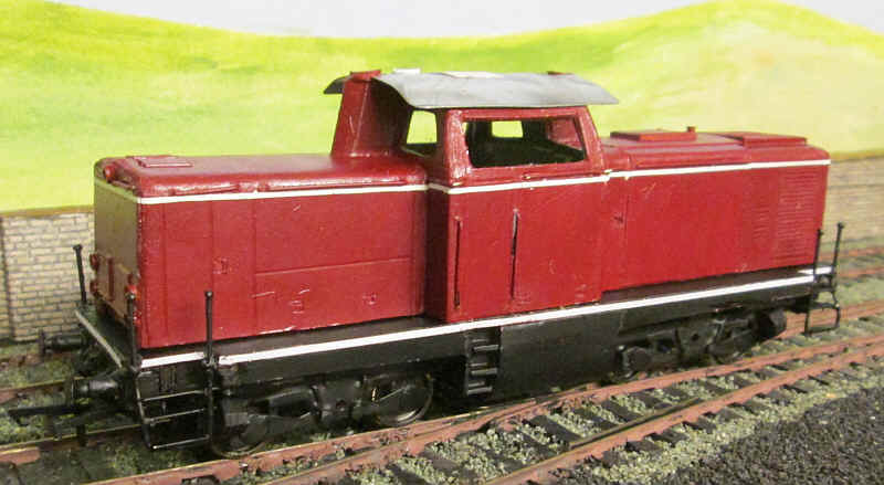
The model has now been painted using Humbrol No.20 maroon and lined using Pressfix white line transfers (from a sheet for BR mineral wagons). The transfers have been sealed with a coat of matt varnish.
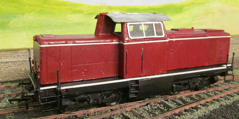
I've now added the cab windows on one side. A very thin band of epoxy resin was applied around the window opening and the completed glazing unit laid onto this. A steady hand is needed for this task!
The final task was to apply the waterslide transfers which were made specially for me by Andreas Nothaft. See his website at http://www.modellbahndecals.de.