LMS Coaches
Suburban coaches
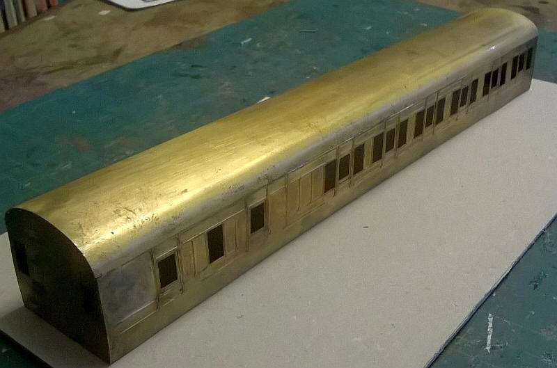
Having obtained two LMS Period 2 suburban coach kits that have been partly assembled I've now started work on them. The etched brass sides are very flimsy so I've decided on a slightly unusual method of construction.
The ends already had the steps and the mounting plates to fix the floor in place soldered together. The sides were then soldered to the ends and the roof was tack soldered to the ends and sides. Once happy with the fit solder was flooded along the inside of the joint between the top of the sides and the edges of the roof. This results in a much stronger body at the top.
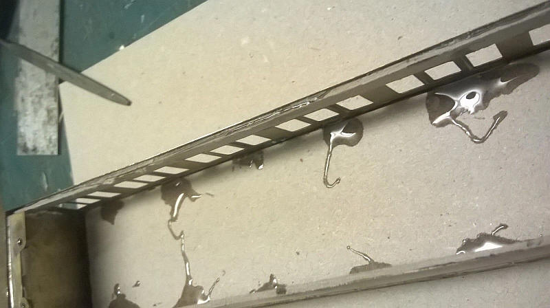
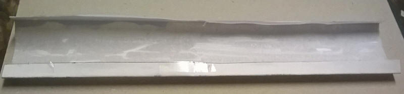
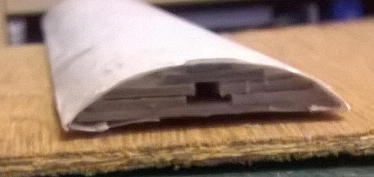
However, the lower edges of the body were showing signs of not being absolutely flat so the next stage was to strengthen the insides of the lower body side where the "tumble home" curve is. A length of 1mm thick card about 8mm wide was glued with epoxy to the inside of the sides positioning the card so the metal floor will sit on top of the card strip but in between the brass sides.
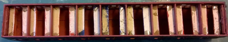
Also visible in the photo above (looking up into the body) is the false ceiling that has been glued in place. The epoxy has been allowed to run down between the edge of the card and the brass. The next stage will show why I decided to have a ceiling.
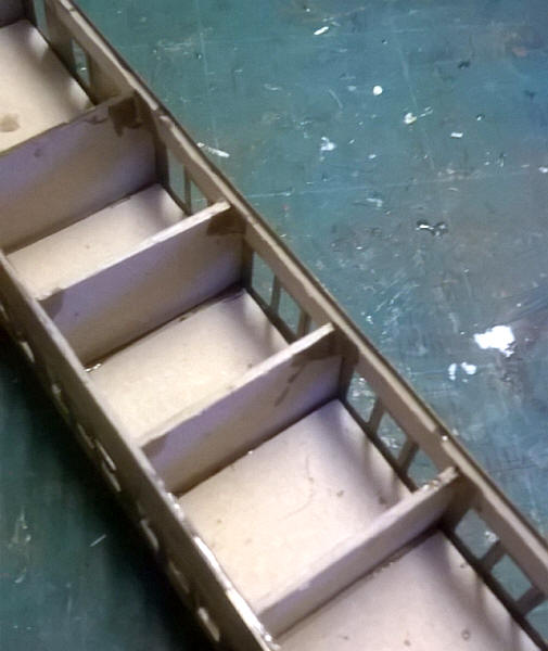
Another view looking up into the body towards the ceiling.
The compartment walls have been added and are fixed to the false ceiling and also to the card strengthening strips on the body sides. A rectangle of card has been glued to the ceiling of each compartment with a small gap behind the windows. This will be used to trap the glazing. The seats will be added after the model is painted and the glazing in place.
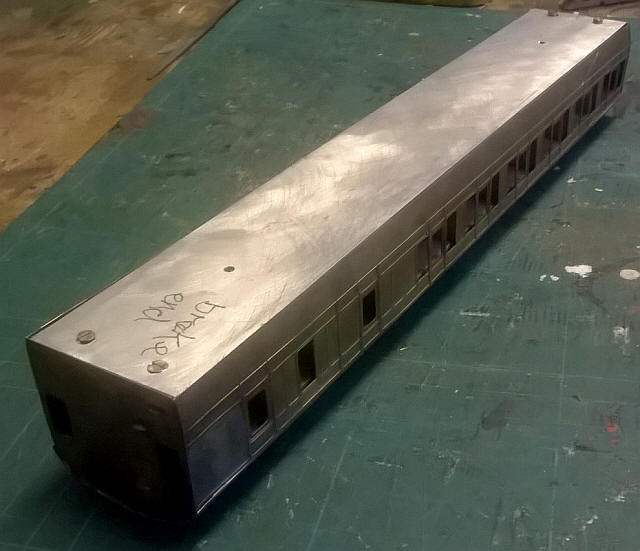
The aluminum carriage floor is now in place. The coach under frames will be built directly on this.
Building a carriage from paper and cardboard
If I am going to build some more LMS carriages I will need a way of producing the roofs. Building on my experiences with Midland coaches I've decided to try to find a way to mass produce them using paper and cardboard.
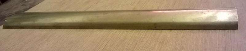
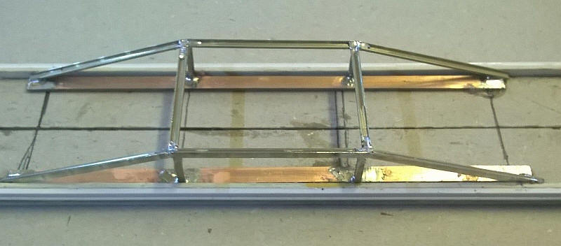
The two metal carriages come with an etched brass roof which have already been curved to the correct profile. I decide to use this as a former.
The first step is to cut a piece of A4 printer paper to the correct length and about 20 mm wider than the curved distance around the roof. It is then wrapped round the brass roof with flaps overlapping the edge of the brass roof. They are temporarily secured to the underneath of the brass with sellotape. These flaps will be used to secure the roof in place later.
The paper is then coated with a thin layer of epoxy resin adhesive and a second layer attached and left until the epoxy has hardened. The paper will require gentle pressure to ensure it is fully attached to the first layer of paper. It's also important to make certain that there is a sharp fold at the edge of the roof. Once dry the brass roof can be carefully slid out from under the paper.
The epoxy resin will ensure that the paper retains its correct shape. A 265mm length of thick (1mm) card was cut to the correct width of 42mm for the base of the roof. This is slightly shorter than the actual roof itself to allow for the ends of the carriage body. The paper roof can then be stuck to the card using the flaps
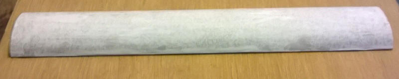
A third layer of paper is added and this is the resulting roof which is surprisingly rigid.
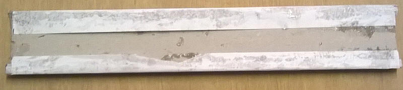
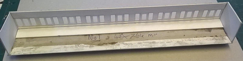
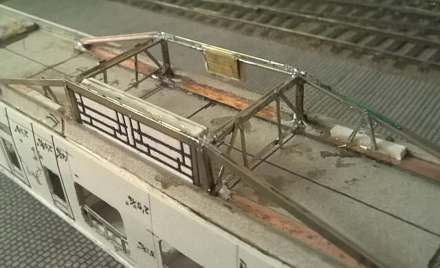
However, to strengthen it further more strips of card were glued in place under the roof. The outer edges were filed to an angle of about 30 degrees and adhesive applied along this edge. The photo shows the stepped layers with a final layer running along the centre line of the roof to give a firm support for the roof ventilators.
Later versions of these cardboard roofs were refined slightly. As mentioned above the base of the roof structure was 42mm. A further 7 layers of 1mm thick mounting board, all 265mm long were glued inside the roof. In descending order these were 40, 38, 36, 34, 28, 22 and 14mm. A final 5mm strip of thin card was glued along the centre line of the roof. This gives an accurate profile to the roof and should allow easy repetition when constructing more card carriages.
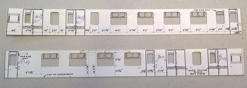
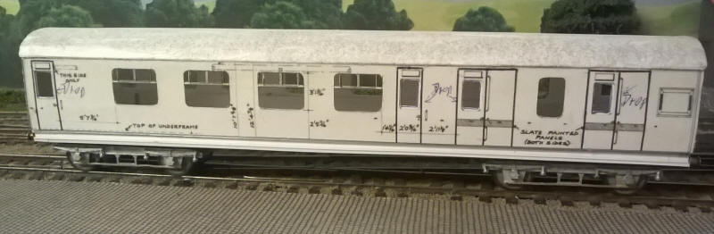
The book "Historic Carriage Drawings Volume 2 LMS and Constituents" contains large numbers of 4mm scale drawings. To complete a rake of three suburban coaches I'd need a composite but I decided to model a Period 3 coach (rather than a paneled Period 2 like the two brass coaches I had in kit form). The Period 3 one is also flush sided so will be easier to build and will be a good model to test techniques for the Stanier express coaches I will need.
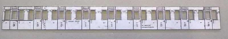
The photo above shows the completed side. The sides were printed out on thin card and the full sized door window openings cut out. Then a strip of printer paper was glued behind the window area. The compartment and door droplight windows were then cut out.
Two long strips of mounting board ( one 3mm wide and the other 10mm wide) were cut to length and glued above and below the windows respectively. This give the sides rigidity and will also give space for the glazing strips.
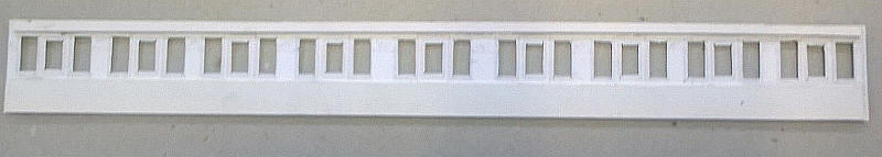
A 15mm wide strip of card was glued to the bottom of the roof to give a firm locating point for the top of the sides. The sides were then glued in place with contact adhesive to give the result...
...as seen here.
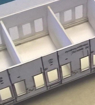
To strengthen the sides further compartment walls were cut from mounting card to fit tightly against the sides and false roof ceiling. Notches were cut around where the longitudinal strengthening strips of card were located.

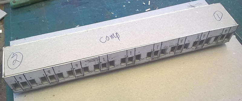
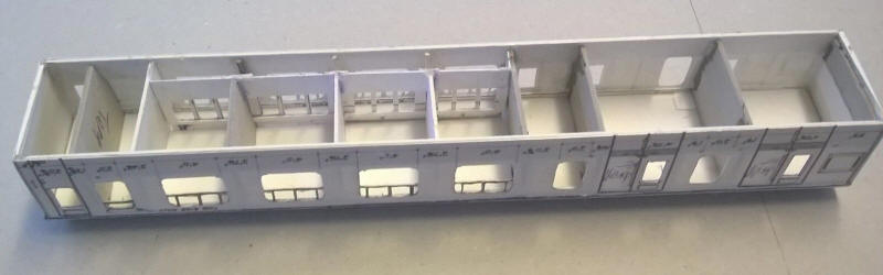
The completed body shell. Just visible is the narrow strip of the card that has been added to the upper strengthening strip of card just above the windows. This will trap the glazing at the top requiring just a few dots of adhesive to be needed at the bottom of the window. At each end of the vehicle there are two strips of mounting board glued to the inner side of the ends. These will act as supports for the coach floor/ chassis unit and also give a more securing fixing point for the steps on the ends of the vehicle.
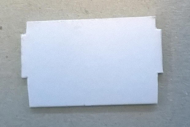
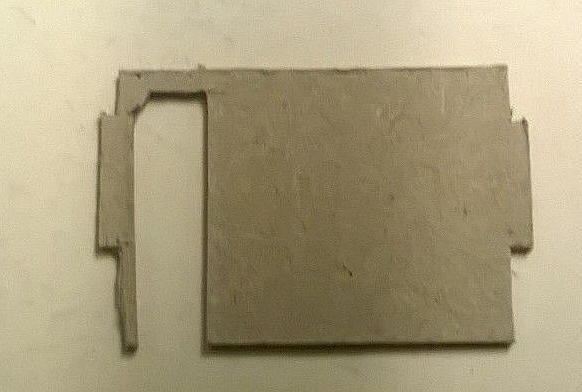
A piece of thick grey mounting has been cut to fit tightly inside the body. The basic body structures for the suburban coaches are now complete so my attention now turns to producing the bodies for LMS Period 3 coaches.
Corridor coaches
I had expected that producing the sides for the Period 3 Stanier corridor coaches would be much more difficult than the suburban coaches. However, this proved not to be the case.
The corridor coaches all have distinctive rounded corners to the windows. I reproduced these by making 3 or 4 tiny cuts with the sharp point of a scalpel blade. The top sliding windows were also quite easy to do. The sharp point of an old pair of compasses was used to make pin pricks at the corner of each opening. Careful work with the scalpel is needed but eventually all the windows were opened up. After cutting out each windows I coated the rear of the windows frames with superglue. This soaks in to the card and also forms a hard surface of glue on the rear of the frame. The result is almost as strong as etched brass. A sharp biro point was drawn around all the door openings before assembly began.
Construction of the body then followed the methods described above for the non-corridor stock with the exception of the compartment walls in the passenger area of this brake 2nd coach.
For these compartment walls I cut partitions with space for the corridor passage. I left a narrow strip of card to give additional support to the carriage wall on the corridor side. This won't be visible from outside once completed.
The main body is now complete with the various compartment walls in place. I've also added the doors and windows between the corridor and the compartments.
Bogies
The two brass kits came with ready assembled white metal bogies but these are no longer available so I had to build my own. The bogies for both the suburban and corridor coaches are more or less the same so I am batch building 8 bogies using a simple method that I used for some of the Midland Railway suburban coaches.
A basic outline was drawn on paper, photocopied multiple times and stuck onto some brass sheet. The axles holes were drilled and opened up to allow bearings to be inserted. The brass was cut roughly to shape as seen here using sharp scissors. The slight inaccuracies are hardly noticeable once on the track. I'm building models to operate not for a display case!
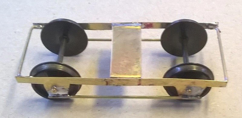
The first bogie has been soldered together. 1mm brass wire has been soldered across the space between the bearing holes. A 10mm wide strip of brass has been folded at each end to give tabs which are then soldered to the bogie side frames. The wheels have been inserted and 1mm brass wire soldered across the ends of the frame.
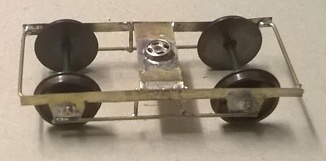
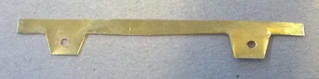
The stretcher bar has now had a hole drilled in it to accept the female part of the press stud which will form the pivot for the bogie. Small lengths of 1mm diameter wire have been soldered in place to represent the secondary suspension of the bogie.
The underframe
Attention now turned to the underframe of the carriages. These will be made in a similar way to the metal bodied carriages using card and plastic.
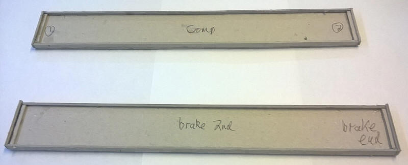
As I am building at least 7 vehicles it seems logical to list the dimensions of the parts for future reference. All card parts were cut from 2mm thick greyboard.
The first two basic underframes are seen above.
Buffer beams are 38mm by 5mm with 27mm buffer centres
The subfloor, which will be glued to the internal coach floor, is 265mm by 34mm. This gives a ledge 2mm wide on either side when glued to the internal floor.
The solebars are 265mm by 5mm and are glued on to the ledge referred to above.
Narrow strips of card are glued behind the bufferbeams to help ensure that the bufferbeams stay vertical.
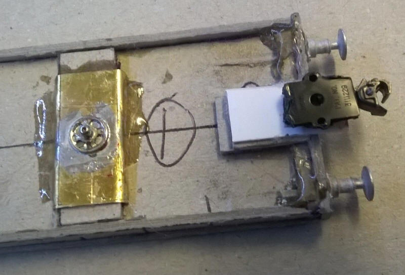
The scratch built bogies are pivoted on a male press stud. This is soldered to a piece of brass which is then glued onto strips of mounting board to give the correct height . 4mm scale LMS coach buffers from Lanarkshire Models & Supplies have been added to the bufferbeams and a Kadee coupling attached at one end.
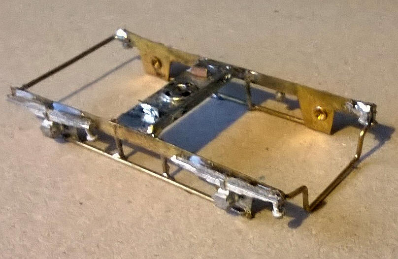
To clear the couplings the cross-wire at one end of the bogie has been modified by bending into a stepped U shape.
The underframe bracing has been added. First of all two lengths of copperclad sleeper strip are glued to the floor.
A 126mm long length of Peco Code 75 rail was bent at the 42m and 84mm lengths using a simple jig. These were then soldered in place. The short vertical lengths and cross pieces were also cut from rail. The flat bottomed side of the rail was placed on the outside to replicate the appearance of the steel sections used.
To complete the underframe details I soldered two cross pieces (out of rail again) and then built up the framework of bracing out of nickel silver strips. The battery boxes were made out of four rectangles of mounting card with a representation of the various opening flaps embossed with a biro - this was copied from the etchings for the two brass carriages. The regulator switch on the opposite side was made from a brass backing plate soldered to the rail frames and then two small rectangles of card were glued to this. On each side of the underframe there is a V iron which was glued to the framework and a card spacing strip. I've not added a brake cylinder as it won't be visible on the model when running.
Back to the bodies
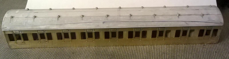
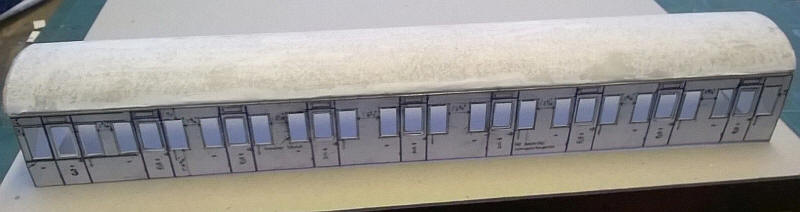
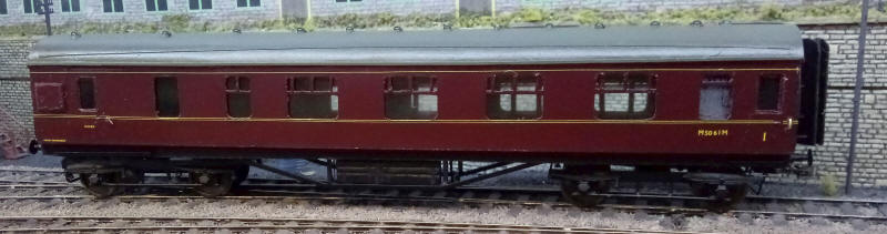
In order to be able to produce future roofs out of paper and card I've decided to fit one of the brass sided carriages with a card roof so that I can continue to make identical roofs for the various models that I have planned using the brass roof as a former. This is the 2nd class vehicle after fitting with rain strips and guttering (fixed in place on the paper roof with liquid polystyrene solvent) as well as torpedo vents (from Lanarkshire Model Supplies).
I also decide that the neatest way to finish off the brass roof on the other coach was to cover the brass with a sheet of printer paper stuck to the brass with epoxy. The rainstrips and guttering can then be fixed in place in the same way.
Door handles and grab rails were also added now.
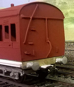
The ends of the carriages have quite a bit of detail to be added to them. Still to be added are the coach lighting wires which I appear to have forgotten on this carriage! The bodies have now all been painted in red oxide primer.
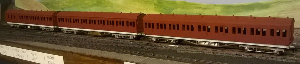
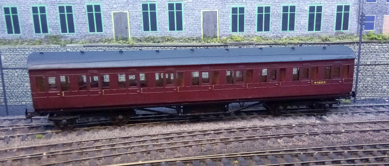
The rake of three suburban coaches ( two Period 2 panelled ones on the left and a flush sided Period 3 on the right).
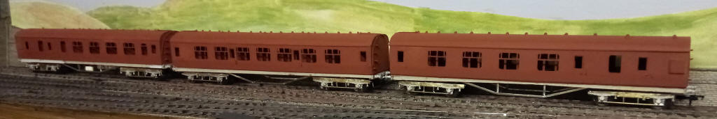
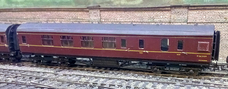
The rake of three corridor coaches. From left to right they are a Brake 3rd, Corridor 3rd and a Brake 1st. All are 57 feet long versions. Ideally I would have preferred a corridor composite rather than a Brake 1st but the composites were 60 feet long and building one of these would make the train too long. Fortunately some of the small number of Brake 1st lasted in service well into the 1960s.
Finishing the models
Obviously, there is still a lot of work to do to finish the models, the first step being to spray the body sides with BR maroon using Railmatch spray cans. Then HMRS Pressfix lining transfers were applied and sealed with several coats of satin varnish. The numbers are Fox transfers with the correct numbers made by cutting up sections of their BR Mark 1 coach number transfers.
After spraying the glazing was inserted. Each compartment needs an individual piece cutting to size and then locating in the slot I'd built in at the top of the window as seen below. Small drops of epoxy were used to hold the glazing in place at the bottom and on the sides. This is not a job to be done except when fresh!
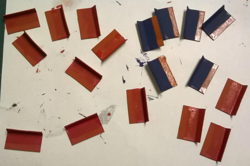
The photo shows the seating units for the suburban coaches - the blue ones are for the first class compartments. They are simply a piece of 1mm thick greyboard cut and folded into an L shape.
The seating units were glued to the compartment walls and the seat bases held in place with drops of epoxy. The seat units also help trap the glazing in place so hopefully there won't be any instances of the glazing falling out.
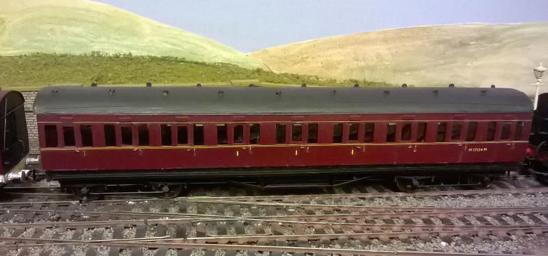
The first to be finished was the Period 3 card bodied composite suburban coach.
Period 2 panelled Brake 2nd in BR unlined maroon.
Period 2 panelled 2nd in BR unlined maroon.
The corridor coaches were treated in exactly the same way. The frosted glazing in the toilet windows were represented by filing the rear of the glazing to craze the surface.
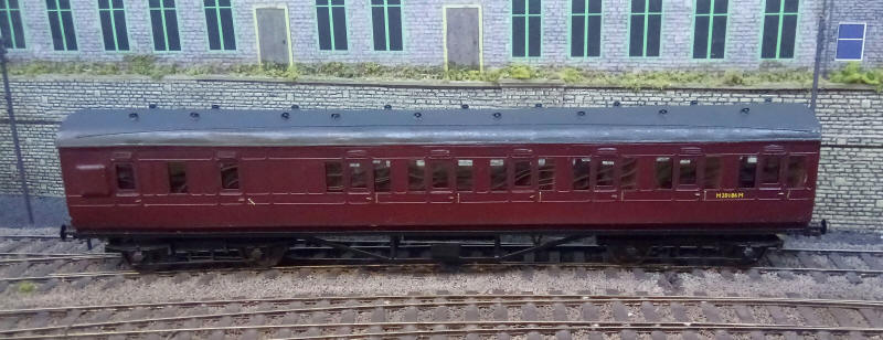
Period 3 57' Brake 1st
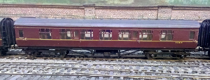
2nd class corridor seen from the corridor side.
Brake 2nd.
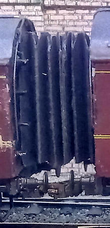
The corridor connections were made out of thick black paper folded to make a concertina and allow the coaches to be coupled but without an unsightly gap. The coaches can be propelled through 4 foot radius crossover curves without derailing.
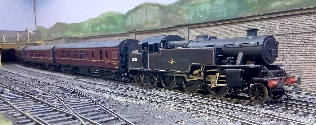
Although the coaches won't be run on my Halifax Midland layout, as the platforms are too short, I've photographed them in this location because of the good lighting. The Fairburn 2-6-4T is a model built, I believe, by Alan Gibson from one of his own kits. I've had to do quite a bit of modifications to it mechanically to get to run on my layouts. It's also had coupling loops made out of brass wire with a buffing plate of brass strip soldered to the wire. This bar allows the loco to propel trains without buffer-locking.
This completes the stock of carriages needed for my LMR layout, although some bogie parcels vans might appear in due course.